Screw full-bridge pilot structure

A pilot stage, screw technology, applied in the direction of fluid pressure actuation device, servo motor assembly, mechanical equipment, etc., to achieve the effect of low processing difficulty, simple structure and flexible control mode

Inactive Publication Date: 2009-12-09
BEIHANG UNIV
View PDF0 Cites 7 Cited by
  • Summary
  • Abstract
  • Description
  • Claims
  • Application Information

AI Technical Summary

Problems solved by technology

[0003] In order to solve the problems existing in the existing servo valves, the present invention proposes a novel helical full bridge pilot stage structure, which has high practical significance for the development of new hydraulic and pneumatic helical full bridge pilot stage servo valves

Method used


Image

  • Screw full-bridge pilot structure
  • Screw full-bridge pilot structure
  • Screw full-bridge pilot structure

Examples


Embodiment Construction

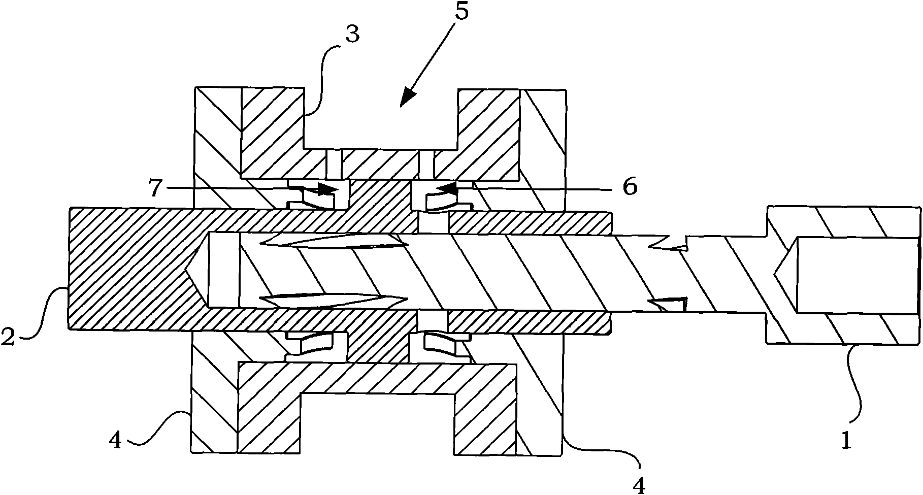
[0022] The spiral pilot stage structure of the present invention will be further described in detail below in conjunction with the accompanying drawings and examples.

[0023] The present invention provides a spiral pilot stage structure, such as figure 1 As shown, the structure includes a pilot control rod 1, a secondary moving piston 2, a piston cylinder 3, and a piston end cover 4. The piston cylinder 3 is set outside the secondary moving piston 2 and fixed by the piston end cover 4 , the piston end cover 4 plays the role of sealing and limiting the displacement of the secondary moving piston 2, and the pilot control rod 1 reciprocates or linearly moves inside the secondary moving piston 2 to realize the linear movement of the secondary moving piston. The following uses hydraulic pressure as an example to illustrate the spiral pilot stage structure of the present invention, and the pneumatic situation is also applicable.

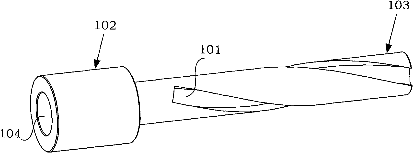
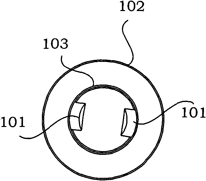
[0024] Such as figure 2 Shown is a schematic dia...


PUM


Abstract

The invention belongs to the technical field of hydraulic pneumatic servo control and discloses a screw full-bridge pilot structure. The screw full-bridge pilot structure comprises pilot control rods, a secondary moving piston, a piston barrel and a piston end cap; in the structure, a smaller pilot control rod is driven by a motor to rotate or move in a straight line in the secondary moving piston to coordinate with the piston barrel and the piston end cap to change a hydraulic or pneumatic damping full-bridge to push the secondary moving piston to move, so as to achieve hydraulic or pneumatic amplification, and the structure can be widely used in two-stage proportion servo valve design. Compared with traditional nozzle baffle or jet pilot structure, the pilot structure has the following advantages: the amplification factor of the pilot is large, thus facilitating the manufacture of proportional valve and servo valve with large flow; the pilot control rods have very small rotary inertia and inertness, and extremely small loaded moment or carrying capacity, thus facilitating the control and improvement of dynamic performance; the pilot structure is simple and is convenient for processing; the pilot structure reduces the requirement on oil cleanliness and improves the work reliability of the pilot.

Description

technical field [0001] The invention belongs to the technical field of hydraulic and pneumatic servo control, and relates to a novel hydraulic or pneumatic helical full-bridge pilot stage structure. Background technique [0002] In the field of hydraulic and pneumatic servo control technology, servo valve is the key component of hydraulic and pneumatic fluid servo control technology. Due to the existence of hydraulic power, it requires a lot of driving force to push the spool of hydraulic and pneumatic servo valve with large flow rate. The current It is difficult for the electromechanical actuator to achieve the purpose of direct driving, so the servo valve with large flow rate generally adopts two-stage or three-stage control. The traditional nozzle baffle or jet tube valve adopts two-stage hydraulic and pneumatic amplification, which solves the design problem of large flow valve, but its disadvantages are difficult processing, high requirements for oil cleanliness, and low...

Claims


Application Information

Patent Timeline
Patent Type & Authority Applications(China)
IPC IPC(8): F15B13/02
Inventor 吴帅焦宗夏阮健T﹒R﹒巴顿俞军涛
Owner BEIHANG UNIV
Why Eureka
Try Eureka