Needle head separating mechanism for automatic needle head separator

A separation mechanism and automatic separation technology, applied in the direction of needles and instruments introduced into the body, can solve the problems of affecting the clamping degree, wear, and large rigid friction between the guide block and the needle puller, so as to avoid excessive rigidity and shorten the use The effect of longevity

Pending Publication Date: 2019-05-10
ZHEJIANG HUAFU MEDICAL EQUIP
View PDF0 Cites 2 Cited by
  • Summary
  • Abstract
  • Description
  • Claims
  • Application Information

AI Technical Summary

Problems solved by technology

However, due to the fixed structure of the guide block and the needle puller in the prior art, the rigid friction between the guide block and the needle puller is relatively large, and the wear is serious after a certain period of use, which affects the resistance of the guide block to the pressure of the needle. The degree of clamping of the pliers will affect the effect of pulling out the needle

Method used


Image

  • Needle head separating mechanism for automatic needle head separator
  • Needle head separating mechanism for automatic needle head separator
  • Needle head separating mechanism for automatic needle head separator

Examples


Embodiment Construction

[0035] combine Figure 1 to Figure 7 The needle separation mechanism used in the automatic needle separation device of the present invention will be further described.

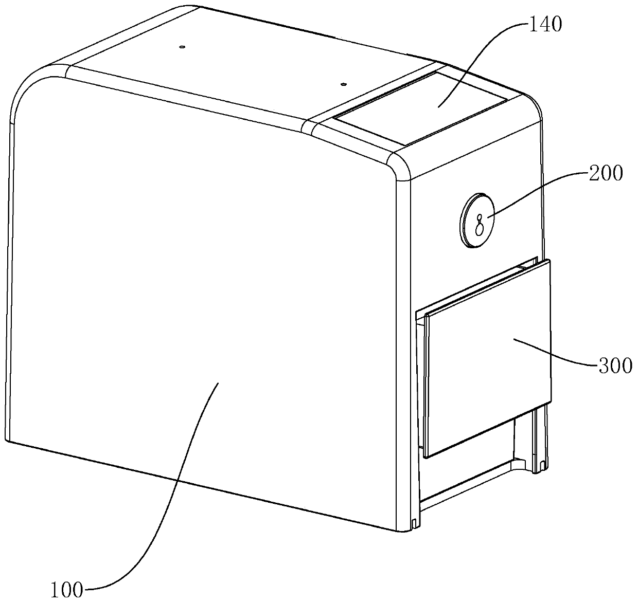
[0036] A needle separation mechanism for an automatic needle separation device, comprising a casing 100, a needle separation mechanism 400, a needle linkage switch 200 and a collection container 300;

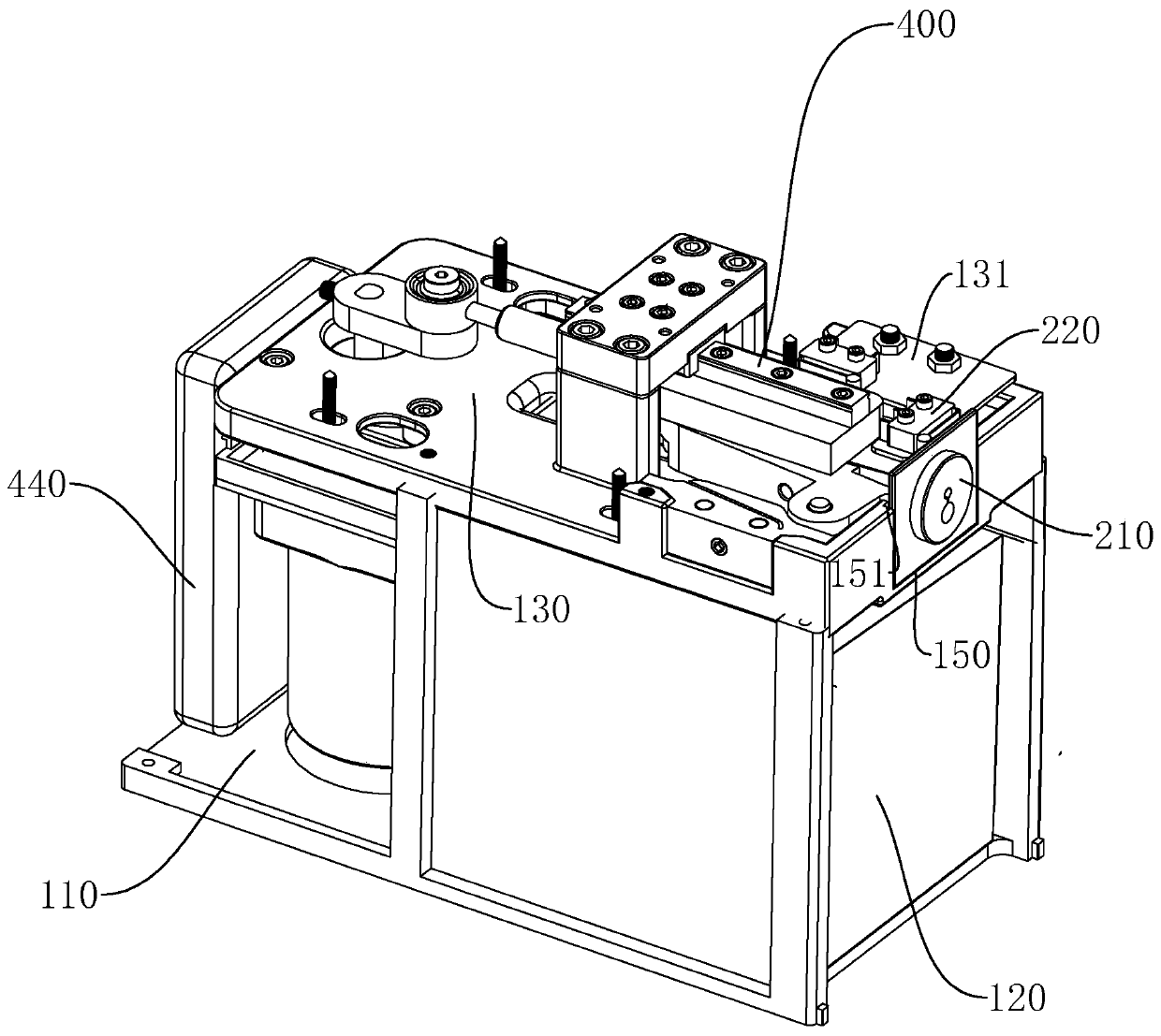
[0037] The casing 100 has an installation cavity. In this embodiment, the installation cavity is divided into a front installation cavity 120 , a rear installation cavity 110 and an upper installation cavity 130 , and the installation cavities are separated by partitions.

[0038] The pin linkage switch 200 is installed on the side wall of the casing 100, and is electrically connected with the electrical components in the needle separation mechanism 400 to drive the needle separation mechanism 400 to operate. The pin linkage switch 200 has a pin Mouth 230;

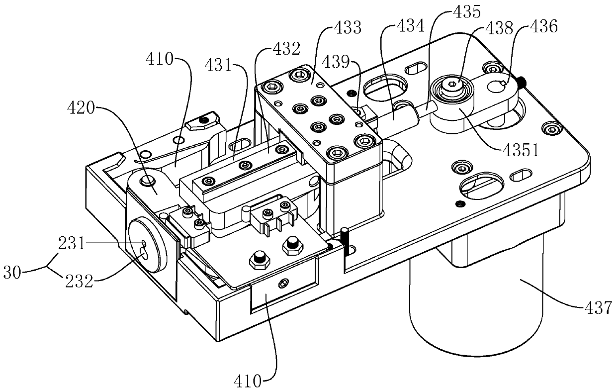
[0039] The needle separation mechanism 400 is arrang...


PUM


Abstract

The invention discloses a needle head separating mechanism for an automatic needle head separator. The needle head separating mechanism comprises guide blocks, needle pulling-out tongs and a driving assembly. The driving assembly is connected with the needle pulling-out tongs. The needle pulling-out tongs comprise a first tong arm, a second tong arm and an elastic part. The first tong arm is hinged to the second tong arm, a needle pulling-out opening corresponding to a needle inserting opening is formed between the first tong arm and the second tong arm, and the elastic part is arranged in theneedle pulling opening and provides opening force for the needle pulling-out opening. Guide parts are arranged on the outer side of the second end of the first tong arm and the outer side of the second end of the second tong arm. The guide blocks are located on the two sides of the needle pulling-out tongs, elastic guide driving parts in sliding fit with the guide parts are arranged on the guideblocks, and when the guide parts move to pass through the elastic guide driving parts, the elastic guide driving parts drive the needle pulling-out opening to be clamped. In the guide fit process of the guide blocks and the needle pulling-out tongs, deformation can be generated, and the situation that the contact rigidity of the guide blocks and the needle pulling-out tongs is too large, so that the service life is shortened is avoided.

Description

technical field [0001] The present invention relates to a separation device, more particularly, to a needle separation mechanism for an automatic needle separation device that pulls out a metal injection head. Background technique [0002] In clinical nursing work, infusion is the most basic, most common, and most intensive nursing operation. According to the requirements of hospital infection management, in order to avoid environmental pollution and re-transmission of diseases, disposable syringes should be destroyed on the spot after use. Clinically, nursing staff often separate the infusion needle from the syringe by hand, cut off the metal injection head of the needle with scissors and put it into the sharps box, which may easily cause needle stick injuries during operation, bringing safety hazards to medical staff. [0003] Therefore, a needle pulling device has appeared in the prior art. The needle pulling device includes needle pulling pliers and guide blocks located ...

Claims


Application Information

Patent Timeline
Patent Type & Authority Applications(China)
IPC IPC(8): A61M5/32
Inventor 王维文
Owner ZHEJIANG HUAFU MEDICAL EQUIP
Why Eureka
Try Eureka