Equipment for cutting metal pipes

A metal pipe and equipment technology, applied in the field of metal pipe cutting equipment, can solve the problems of inability to adjust the cutting length, cumbersome operation, and lack of fixed-length functions, and achieve the effects of easy traction, improved flexibility, and easy movement

Active Publication Date: 2020-06-30
无锡必胜必精密钢管有限公司
View PDF7 Cites 0 Cited by
  • Summary
  • Abstract
  • Description
  • Claims
  • Application Information

AI Technical Summary

Problems solved by technology

Due to technological requirements, some metal pipes need to be cut to fixed length during processing, and most of the general cutting equipment does not have the function of fixed length, and needs to be measured manually when using, which is cumbersome to operate, and some cutting equipment has the function of fixed length, but However, it cannot conveniently adjust the cutting length, which has certain limitations.

Method used


Image

  • Equipment for cutting metal pipes
  • Equipment for cutting metal pipes
  • Equipment for cutting metal pipes

Examples


Embodiment 1

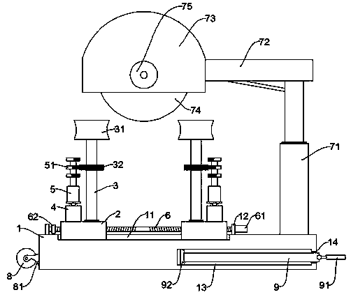
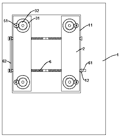
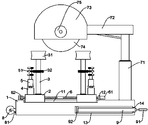
[0023] see Figure 1~2 , in an embodiment of the present invention, a metal pipe cutting device includes a cutting assembly for cutting the pipe and a clamping assembly for clamping and transporting the pipe, both the cutting assembly and the clamping assembly are arranged on a base 1; The cutting assembly includes a second lifting rod 71 and a cutting knife 74, the second lifting rod 71 is installed on the base 1, a connecting frame 72 is fixed on the top of the movable end of the second lifting rod 71, and a protective shell is connected to the end of the connecting frame 72 73, the cutting knife 74 rotates and connects the protective shell 73, and the cutting motor 75 that drives the cutting knife 74 to rotate is installed on the protective shell 73. During work, the cutting knife 74 is driven by the cutting motor 75 to rotate, and the second elevating rod 71 drives the cutting The knife 74 lifts to complete the cutting of the pipeline;

[0024] The clamping assembly inclu...

Embodiment 2

[0030] see Figure 3-4 , the embodiment of the present invention is improved on the basis of embodiment 1, mainly to improve the overall flexibility of use, specifically:

[0031] One side of the base 1 is provided with a roller 8, the roller 8 is rotatably connected to the roller bracket 81 fixed on the base 1, and the lower surface of the roller 8 is higher than the lower surface of the base 1, so that in normal working condition, the roller 8 will not Contact with the ground will not affect the stability of the equipment, and when the equipment needs to be moved, just tilt the base 1 so that the rollers 8 are in contact with the ground;

[0032] Optionally, a pull rod 9 is also included. The pull rod 9 is arranged on the side of the base 1 opposite to the roller 8. A handle 91 is hinged on the pull rod 9. When moving, the pull rod 9 can be used to pull the overall equipment, which is more convenient to use;

[0033] Further, the base 1 is also provided with a storage cavit...


PUM


Abstract

The invention discloses equipment for metal pipeline cutting, and relates to the field of machining. The equipment mainly realizes fixed length cutting of a pipeline. The equipment comprises a cuttingassembly for cutting the pipeline and a clamping assembly for clamped transporting the pipeline, wherein the cutting assembly and the clamping assembly are arranged on a base, the clamping assembly comprises two supporting seats symmetrically arranged on the base; rotating shafts are rotationally connected to the top of the supporting seats, guide wheels are fixed to the tops of the rotating shafts, complete gears are fixed on the periphery of the middle shaft bodies of the rotating shafts, driving motors are further installed on the supporting seats, the shaft extension ends of the driving motors are provided with a first lifting rods, a plurality of incomplete gears are fixed on the periphery of the movable end rod bodies of the first lifting rods, and the number of teeth of the plurality of incomplete gears is gradually increased from top to bottom. According to the equipment, the complete gears and the incomplete gears are arranged to complete the fixed-length cutting work; and the cutting length is adjusted through the first lifting rods and the plurality of incomplete gears.

Description

technical field [0001] The invention relates to the field of mechanical processing, in particular to equipment for cutting metal pipes. Background technique [0002] A pipeline is a device used to transport gas, liquid or fluid with solid particles connected by pipes, pipe connectors and valves. Usually, after the fluid is pressurized by blowers, compressors, pumps and boilers, it flows from the high-pressure part of the pipeline to the low-pressure part, and it can also be transported by the pressure or gravity of the fluid itself. Pipes are widely used, mainly in water supply, drainage, heat supply, gas supply, long-distance transportation of oil and natural gas, agricultural irrigation, hydraulic engineering and various industrial devices. [0003] Pipes can be divided into metal pipes and non-metal pipes according to different materials. Metal pipes need to be cut during processing. Due to technological requirements, some metal pipes need to be cut to fixed length duri...

Claims


Application Information

Patent Timeline
Patent Type & Authority Patents(China)
IPC IPC(8): B23D21/00B23D33/00B23D33/02
Inventor 于海青王金涛滕向华梁宁宁单鑫
Owner 无锡必胜必精密钢管有限公司
Why Eureka
Try Eureka