
Improved prestressed cable movable guardrail structure

A technology of prestressed cables and movable guardrails, applied in the directions of roads, road safety devices, roads, etc., can solve the problems of lack of adaptability, difficult to replace and maintain, and easy to trip, so as to enhance the safety and overall safety of the guardrail. performance, easy to maintain and open, increase the effect of the guide tube structure

Inactive Publication Date: 2020-05-29
赤壁市亿德汽车配件有限公司
View PDF0 Cites 0 Cited by
  • Summary
  • Abstract
  • Description
  • Claims
  • Application Information

AI Technical Summary

Problems solved by technology

This road section is prone to vehicles crossing the guardrail with openings in the middle divider and colliding with opposing vehicles, causing vicious secondary accidents
[0003] The existing steel pipe prestressed cable movable guardrail can effectively intercept out-of-control vehicles, but at the same time there are some shortcomings: 1. The existing butterfly plate transverse connection components are expensive to manufacture and cause a lot of waste of materials; the existing Japanese-shaped The uprights on both sides of the horizontal connecting member are prone to tripping, which poses a safety risk
2. The existing longitudinal connection method of inner and outer casings is expensive, difficult to install, and not suitable for curved road sections
4. The existing end frame column adopts piling type, which is not easy to replace and maintain
5. The existing end frame structure is not adaptable in length, and there are many large errors in the opening length of the middle belt, which makes installation difficult

Method used


Image

  • Improved prestressed cable movable guardrail structure
  • Improved prestressed cable movable guardrail structure
  • Improved prestressed cable movable guardrail structure

Examples


Embodiment Construction

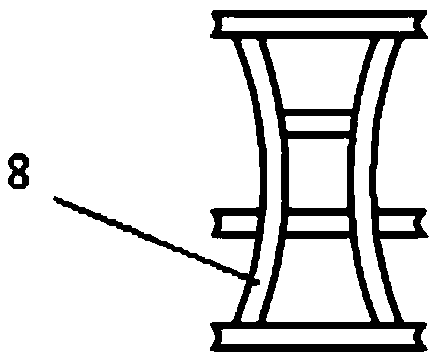
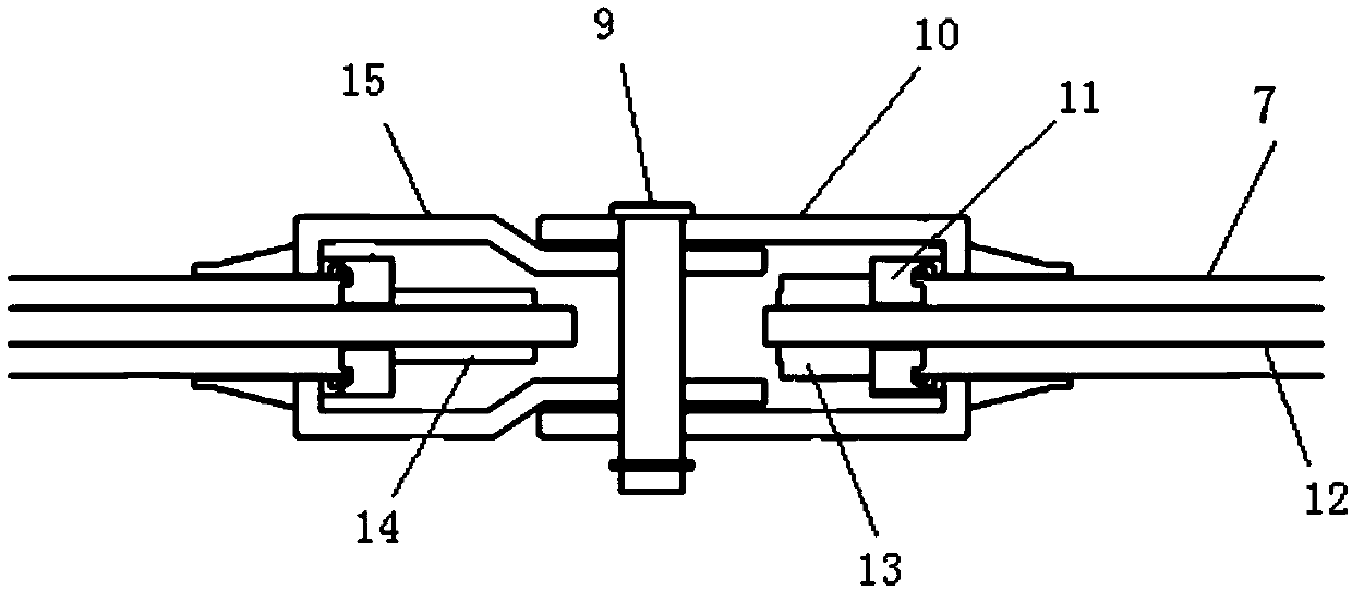
[0028] The following will clearly and completely describe the technical solutions in the embodiments of the present invention with reference to the accompanying drawings in the embodiments of the present invention. Obviously, the described embodiments are only some, not all, embodiments of the present invention. All other embodiments obtained by those skilled in the art based on the embodiments of the present invention belong to the protection scope of the present invention.

[0029] Such as figure 1 As shown, an improved prestressed cable movable guardrail structure of the embodiment of the present invention includes: a middle frame 3, a middle connecting member 4, an end anchoring frame 5, an end connecting rod 6 and a front opening member 1, the described The middle frame 3 is a truss formed by welding or bolting the steel pipe cross beam 7 through the anti-stumbling member 2. The steel pipe cross beam 7 is provided with a steel cable 12, and the steel cable 12 is fixed at ...


PUM


Abstract

The invention discloses an improved prestressed cable movable guardrail structure. The structure comprises a middle frame, a middle connecting component, an end anchoring frame, an end connecting rodand a front opening component, the middle frame is a truss formed by welding or bolted connection of steel pipe cross beams through anti-tripping components; steel wire ropes are arranged in the steelpipe cross beam; the steel wire ropes are fixed at two ends of the steel pipe cross beam; the middle connecting component is connected with the ends of the steel pipe and the steel wire ropes, the bottom of the end anchoring frame is fixedly connected to the ground, guide pipes are arranged on the two sides of the end anchoring frame, the end connecting rod penetrates through the guide pipes, oneend of the end connecting rod is connected with the middle frame through the front opening component, and the other end of the end connecting rod is fixed to the connecting end of the middle frame.

Description

technical field [0001] The invention relates to the technical field of high-speed protection, in particular to an improved prestressed cable movable guardrail structure. Background technique [0002] The movable guardrail is set at the opening of the central divider of the expressway, in order to facilitate the passage of special vehicles such as traffic accident handling vehicles and emergency vehicles in emergency situations and temporarily open and release when the road construction on one side is closed. This road section is prone to vehicles crossing the guardrail with openings in the middle section and colliding with opposing vehicles, causing vicious secondary accidents. [0003] The existing steel pipe prestressed cable movable guardrail can effectively intercept out-of-control vehicles, but at the same time there are some shortcomings: 1. The existing butterfly plate transverse connection components are expensive to manufacture and cause a lot of waste of materials;...

Claims


Application Information

Patent Timeline
Patent Type & Authority Applications(China)
IPC IPC(8): E01F15/12E01F15/04
CPCE01F15/0407E01F15/0423E01F15/12
Inventor 钱金河
Owner 赤壁市亿德汽车配件有限公司
Learn More