Welding robot capable of moving in all directions

A welding robot, omnidirectional moving technology, applied in welding equipment, auxiliary welding equipment, welding/cutting auxiliary equipment, etc. To move the function, meet the needs of use, the effect of compact structure

Inactive Publication Date: 2019-05-10
航天通用技术(北京)有限公司 +1
View PDF15 Cites 4 Cited by
  • Summary
  • Abstract
  • Description
  • Claims
  • Application Information

AI Technical Summary

Problems solved by technology

As far as the existing welding robot is concerned, the movable range is small, and the working position cannot be changed in a large range according to the adjustment of the production process
If you simply rely on changing the installation position of the welding robot to meet the work requirements, it will inevitably increase the workload and affect the work progress.

Method used


Image

  • Welding robot capable of moving in all directions
  • Welding robot capable of moving in all directions
  • Welding robot capable of moving in all directions

Examples


Embodiment 1

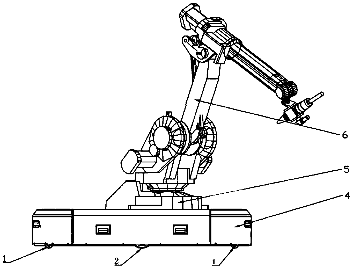
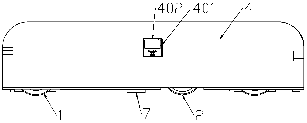
[0029] Such as figure 1 , figure 2 as well as image 3 As shown, a welding robot that can move in all directions includes a vehicle body and a welding robot assembly 6 installed on the vehicle body. The bottom of 4 is provided with chassis 3, and this chassis 3 is provided with driving wheel assembly 2 and driven wheel assembly 1, and described chassis 3 is also provided with first driving motor 101, second driving motor 201, first driving motor The output shaft of 101 is connected with a gear 102, and the gear 102 is meshed with a rack 103, and the rack 103 is movably connected on the chassis 3. Specifically, a slide rail may be set on the chassis, a slider is arranged at the lower end of the rack, and the slider is placed On the slide rail, connecting blocks 104 are fixed at both ends of the rack 103, and each connecting block 104 is movably connected with a first connecting rod 105, and one end of the first connecting rod 105 is fixed to the connecting block 104 through ...

Embodiment 2

[0035] This embodiment is further optimized on the basis of Embodiment 1. Specifically, the differential 204 includes a fixed piece 2041 and four idler gears that mesh with each other and form a square structure, which are respectively the first idler gear 2044 and the second idler gear 2044. Idling gear 2043, the 3rd idler gear 2046 and the 4th idler gear 2045, described first idler gear 2044 is fixed on described drive shaft 205 one end place that is fixed with from gear 203, the 3rd idler gear 2046 is fixed on opposite other On the driving shaft of the driving wheel assembly 1, the second idler gear 2043 and the fourth idler gear 2045 are connected by setting a driven shaft 2042, and the driven shaft 2042 is fixed on the fixing member 2041, and the fixing member 2041 is movably connected On the drive shaft 205; the function of speed regulation is realized. When the output shaft of the second drive motor 201 drives the main gear 202 to rotate, thereby driving the slave gear ...

Embodiment 3

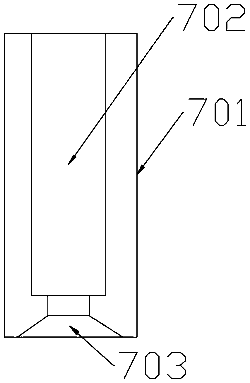
[0037]This embodiment is further optimized on the basis of Embodiment 2. Specifically, the bottom of the chassis 3 is also provided with a support leg 7. The support leg 7 includes a hollow fixed column 701, and a hydraulic cylinder is arranged inside the hollow fixed column 701. 702, one end of the telescopic rod of the hydraulic cylinder 702 is fixed with a support plate 703. In practice, the height of the hollow fixed column 701 is smaller than the height of the driving wheel assembly 2; specifically, the bottom of the support plate 703 is set With rubber pads.

[0038] Because during positioning welding, the movement of the vehicle body may occur, so this setting can use supporting legs for positioning during positioning, which is more conducive to welding and improves welding quality. The setting of rubber pads can also serve the purpose of anti-skid.


PUM


Abstract

The invention discloses a welding robot capable of moving in all directions. A vehicle body and a welding robot assembly installed on the vehicle body are included; the vehicle body comprises a shell,and a chassis is arranged at the bottom of the shell, and is provided with driving wheel assemblies and driven wheel assemblies; a first driving motor and a second driving motor are further arrangedon the chassis; a gear is connected to an output shaft of the first driving motor, and is engaged with a rack which is movably connected to the chassis; a connection block is fixed to each of the twoends of the rack; each connection block is movably connected with a transmission shaft, and the transmission shafts are connected with the driven wheel assemblies; a main gear is connected to an output shaft of the second driving motor, and is engaged with a slave gear; the driving wheel assemblies are each provided with a driving shaft, and the slave gear is fixed to one of the driving shafts; and a differential mechanism is connected between the driving shafts. The welding robot can move in all directions in a narrow space, better meets the using requirement of a user, and is compact in structure, convenient to manipulate and high in practicability.

Description

technical field [0001] The invention relates to the field of welding robots, in particular to an omnidirectional mobile welding robot. Background technique [0002] At present, the commonly used welding robots mainly rely on their own mechanical structure to move when welding different positions. With the rapid development of robot automation and the increase in the complexity of welding production lines, higher requirements are placed on the scope of application of welding robots. As far as the existing welding robot is concerned, the movable range is small, and the working position cannot be changed in a large range according to the adjustment of the production process. If you simply rely on changing the installation position of the welding robot to meet the work requirements, it will inevitably increase the workload and affect the work progress. Contents of the invention [0003] In order to solve the above existing problems, the present invention discloses a welding ...

Claims


Application Information

Patent Timeline
Patent Type & Authority Applications(China)
IPC IPC(8): B23K37/02B23K37/00
Inventor 周林生
Owner 航天通用技术(北京)有限公司
Why Eureka
Try Eureka