Clamping device for grinding screw tap

A clamping device and tap technology, used in grinding drive devices, grinding/polishing safety devices, grinding workpiece supports, etc., can solve the repeated machining errors of the machined surface, the indistinct distinction between the ground and unground areas, etc. problems, to achieve the effect of improving processing quality, good protection and reasonable structure

Inactive Publication Date: 2019-05-10
TAIYUAN UNIVERSITY OF SCIENCE AND TECHNOLOGY
7 Cites 0 Cited by

AI-Extracted Technical Summary

Problems solved by technology

[0003] The purpose of the present invention is to solve the technical problems of the existing tap processing equipment that the distinction between the ground and the unground area is not obvious and...

Method used

[0019] The tap clamping block I4 and the tap clamping block II20 are designed to be in conta...

Abstract

The invention relates to a clamping device for grinding a screw tap, and belongs to the technical field of clamping equipment for tool machining. The clamping device aims to solve the technical problem that existing screw tap machining equipment is not obvious in grinding and non-grinding region distinguishing and easily cause repeated machining errors of machined surfaces. According to the technical scheme, the clamping device for grinding the screw tap comprises a disc connected with a rotating device, and further comprises a clamp part and a protecting part, the clamp part and the protecting part are used for clamping the screw tap, and the clamp part is composed of a first screw tap clamping block, a rack, a bearing, a gear, a clamp base, a first coupler, a first motor, a shaft and a second screw tap clamping block; and the protecting part is composed of a guide rail, a sliding block, a second coupler, two bearings, a bearing seat, a lead screw, an opening and closing nut, a supporting shell, a protection cover and a second motor. The clamping device has the advantages that the structure is reasonable, and the machined screw tap can be well protected and is dustproof and the like.

Application Domain

Grinding drivesOther manufacturing equipments/tools +2

Technology Topic

EngineeringMachining +2

Image

  • Clamping device for grinding screw tap
  • Clamping device for grinding screw tap
  • Clamping device for grinding screw tap

Examples

  • Experimental program(1)

Example Embodiment

[0016] The present invention will be further described below in conjunction with the accompanying drawings and embodiments.
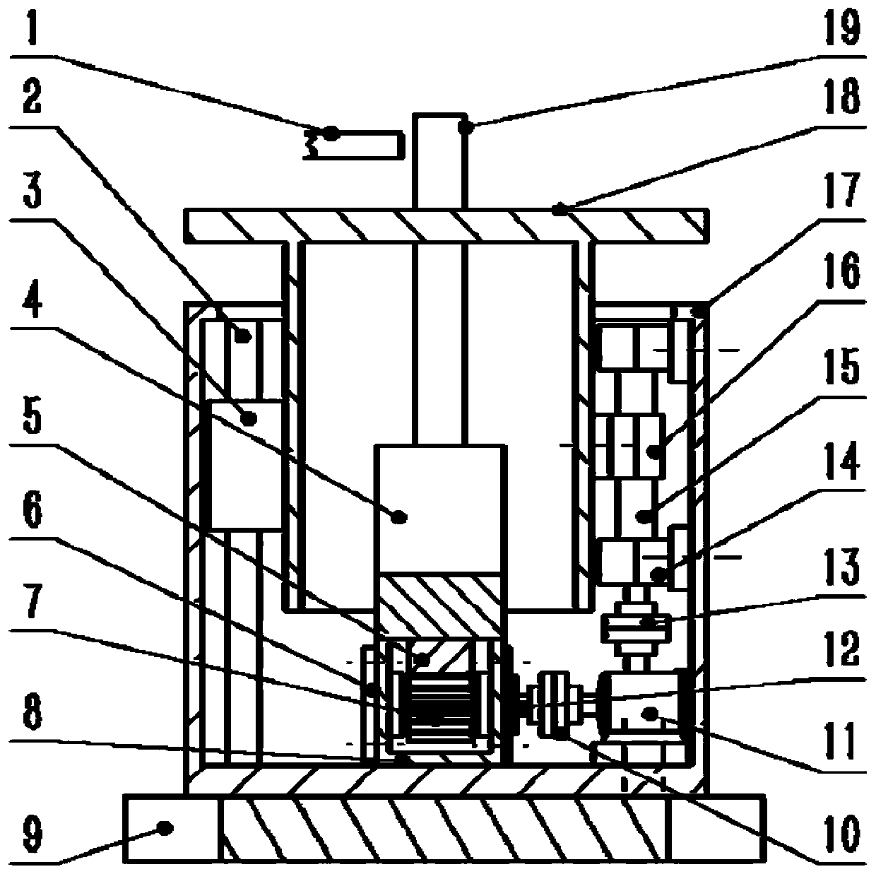
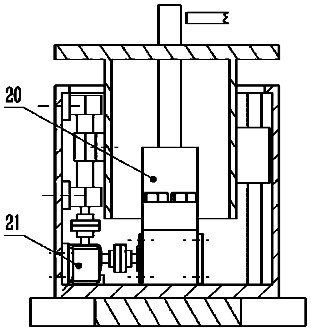
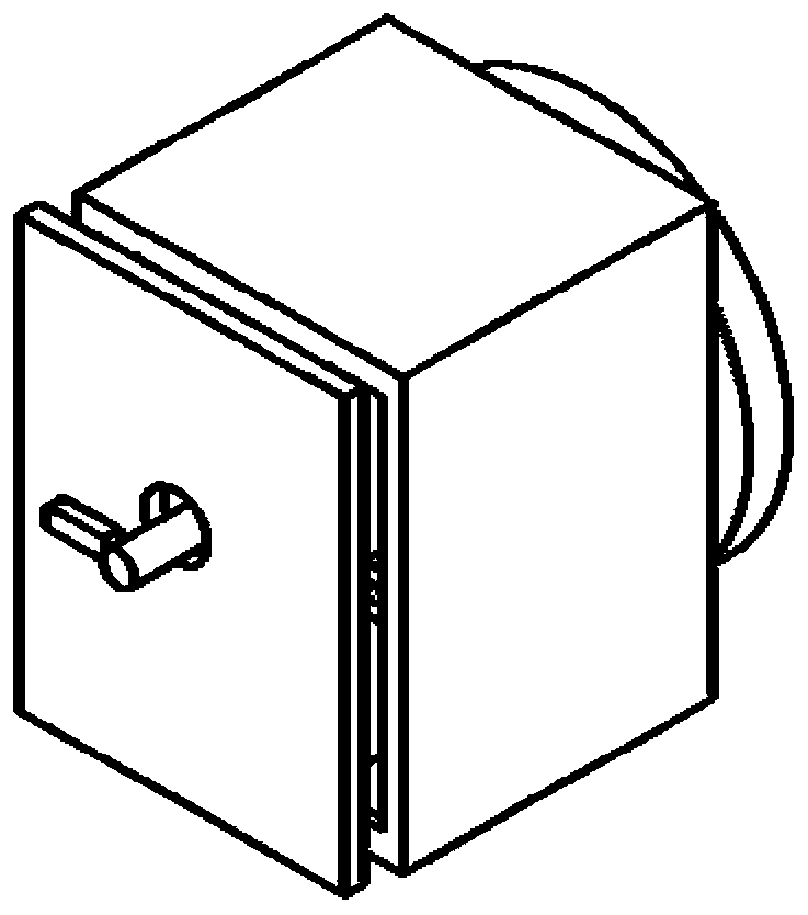
[0017] like Figure 1~5 As shown, a clamping device for tap grinding in this embodiment includes a disc 9 connected with a rotating device, wherein: it also includes a clamping part and a protective part for clamping a tap 19, and the clamping The components are composed of tap clamping block I4, rack 5, bearing 6, gear 7, fixture base 8, coupling I10, motor I11, shaft 12 and tap clamping block II20, and the rack 5 is set on the tap clamping On the bottom surface of the block I4, the tap clamping block II20 is installed on one side of the top surface of the fixture base 8, the other side of the fixture base 8 is provided with a cavity, and the bearings 6 are arranged on the two side walls of the cavity. In the bearing hole, the shaft 12 is installed on the bearing 6 and one end thereof is connected with the shaft of the motor I11 through the coupling I10, the gear 7 is installed on the shaft 12 located in the cavity of the fixture base 8, and the tap The clamping block I4 is installed on the top surface of the fixture base 8 and the rack 5 meshing with the gear 7 is located in the cavity of the fixture base 8; Two bearings and bearing housing 14, lead screw 15, split nut 16, support shell 17, protective cover 18 and motor II 21, the support shell 17 is a thin-walled rectangular opening, and a protective cover is provided on its top surface hole, the guide rail 2 is arranged on one side of the inner cavity of the support housing 17, the slider 3 is arranged on an outer side wall of the protective cover 18 and connected with the guide rail 2, and the two bearings and the bearing seat 14 are arranged on On the inner wall of the support housing 17 opposite to the guide rail 2, one of them is installed on the upper part of the inner wall of the support housing 17, and the other is installed on the middle and lower part of the inner wall of the support housing 17. The screw 15 is installed on the bearing and the bearing seat 14 and one end thereof is connected with the shaft of the motor II21 through the coupling II13, the split nut 16 is installed on the other outer wall of the protective cover 18 and connected with the lead screw 15; the fixture part is installed in the protective part supporting shell The center of the bottom surface of the inner cavity of the body 17, the protective cover 18 is arranged in the protective cover hole of the supporting shell 17 and covers the fixture parts therein, and the motor II21 and the electric motor I11 are installed on the bottom surface of the inner cavity of the supporting shell 17 , the bottom of the supporting shell 17 is connected with the disc 9 .
[0018] The protective cover 18 is a thin-walled part with a rectangular opening, and a feeding port for a tap 19 is provided in the center of its top surface to facilitate the loading and unloading of the tap.
[0019] The tap clamping block I4 and the tap clamping block II20 are designed to be in contact with the tap 19 in a V-shaped groove structure to precisely clamp the tap 19 .
[0020] The motor I11 and the motor II21 are continuously variable speed motors.
[0021] Working process of the present invention is:
[0022] When the tap 19 is ready to be ground, first start the motor Ⅰ11 to drive the gear 7 to rotate, so that the tap holding block Ⅰ4 in the fixture part moves to create a gap with the tap holding block Ⅱ20 fixed on the fixture base 8, and the tap 19 passes through the protection The tap 19 feeding port of the cover 18 is put into the V-shaped groove of the tap clamping block I4 and the tap clamping block II20, and then the motor I11 is controlled to rotate in the opposite direction, so that the tap clamping block I4 moves toward the tap 19; 19 is clamped, and after screw tap 19 is clamped, motor I 11 stops rotating. At this time, the protective cover 18 is at the lowest position. When grinding, the disk 9 connected with the rotating device drives the present invention and the screw tap 19 to rotate, and the emery wheel 1 performs a feed motion relative to the screw tap 19 . While processing, the height of the protective cover 18 can be adjusted by controlling the motor II 21 to drive the lead screw 15 to rotate, so that the protective cover 18 can be protected along with the processed part. When the processing is completed, the motor I11 is controlled to reverse, so that the tap clamping block I4 moves in the opposite direction to the workpiece, the processed tap 19 is taken out, and the protective cover 18 is rotated back through the lead screw 15. The protective cover 18 ensures the processing quality of the screw tap 19 and improves the processing accuracy of the screw tap 19 .

PUM

no PUM

Description & Claims & Application Information

We can also present the details of the Description, Claims and Application information to help users get a comprehensive understanding of the technical details of the patent, such as background art, summary of invention, brief description of drawings, description of embodiments, and other original content. On the other hand, users can also determine the specific scope of protection of the technology through the list of claims; as well as understand the changes in the life cycle of the technology with the presentation of the patent timeline. Login to view more.

Similar technology patents

Electrical box spot welding device

Owner:合肥凯蒙新材料有限公司

Coating machine of battery pole pieces

InactiveCN101937988Aprecise positioninggood packaging
Owner:DONGGUAN HONBRO LI BATTERY EQUIP TECH

Chain-wheel-driven dome base

PendingCN108797872Afor precise controlAccurately control the rotation angle
Owner:南京紫金山光学仪器厂

Classification and recommendation of technical efficacy words

  • Accurately control the rotation angle

Chain-wheel-driven dome base

PendingCN108797872Afor precise controlAccurately control the rotation angle
Owner:南京紫金山光学仪器厂
Why Eureka
Try Eureka