
Electronic mirror dividing plate with dividing distance and impact point position and method thereof

A technology of impact point and reticle, which is applied in the intersection of computer and optical rangefinder, in the field of ballistics, can solve the problems of reducing shooting accuracy and the target cannot know the impact point in time, so as to reduce the error of manual experience judgment, It is convenient to hit the target and improve the effect of hit rate

Pending Publication Date: 2019-05-10
XIANGTAN UNIV
View PDF5 Cites 8 Cited by
  • Summary
  • Abstract
  • Description
  • Claims
  • Application Information

AI Technical Summary

Problems solved by technology

[0003] To sum up, the problem existing in the prior art is that the reticle on the current firearm scope cannot know the position of the impact point in time for the determined target, which directly reduces the shooting accuracy.

Method used


Image

  • Electronic mirror dividing plate with dividing distance and impact point position and method thereof
  • Electronic mirror dividing plate with dividing distance and impact point position and method thereof
  • Electronic mirror dividing plate with dividing distance and impact point position and method thereof

Examples


Embodiment Construction

[0039] In order to make the object, technical solution and advantages of the present invention more clear, the present invention will be further described in detail below in conjunction with the examples. It should be understood that the specific embodiments described here are only used to explain the present invention, not to limit the present invention.

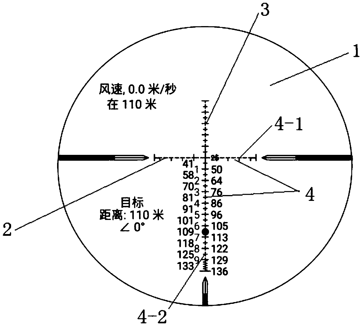
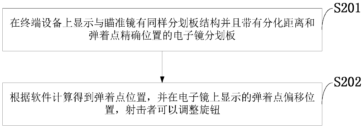
[0040] Aiming at the problem that the reticle on the current gun sight cannot know the position of the impact point in time for the determined target, which directly reduces the shooting accuracy; the present invention has the same reticle structure as the sight on the terminal device and Electronic mirror reticle with differentiation distance and precise position of the impact point, the position of the impact point is calculated according to the software, and the offset position of the impact point is displayed on the electronic mirror.

[0041] The application principle of the present invention will be described in detai...


PUM


Abstract

The invention belongs to the technical field of intersection of ballistics, computers and optical range finders, and discloses an electronic mirror dividing plate with the dividing distance and impactpoint position and a method thereof. The electronic mirror dividing plate includes a dividing plate body, a windage yaw offset line and a trajectory offset line, wherein the windage yaw offset line and the trajectory offset line are vertically intersected on the dividing plate body, the intersection position of the windage yaw offset line and the trajectory offset line is the position of the bullet return-to-zero distance, both sides of the trajectory offset line include the dividing distance and the position of an impact point to be displayed, and a dividing refining line is set on a vertical intersection line. According to the electronic mirror dividing plate with the dividing distance and impact point position and the method thereof, the electronic mirror dividing plate with the same dividing plate structure as a sighting telescope and the dividing distance and impact point precise position is displayed on terminal equipment, the position of the impact point is obtained according to software calculation, a shooter can adjust a knob on the offset position of the impact point shown on an electronic mirror, errors of artificial experience judgment are reduced, the knob can be quickly turned for offset adjustment, and users conveniently and accurately hit targets.

Description

technical field [0001] The invention belongs to the intersecting technical field of ballistics, computer and optical range finder, and in particular relates to an electronic mirror reticle with differentiation distance and impact point position and a method thereof. Background technique [0002] At present, the commonly used existing technology in the industry is as follows: the function of the gun scope is to use the specific differentiation structure of the scope to accurately shoot the target. The sights currently used are divided into mechanical sights and optical sights. Most of them use optical sights, which aim at the center of the sight line in the sight by coincident with the imaging of the target. When aiming and shooting, whether it is aiming posture or shooting experience, it will affect the shooting accuracy of shooting beginners; during the shooting process, the bullet will drop under the action of gravity, shooting angle, wind direction, wind speed, air resist...

Claims


Application Information

Patent Timeline
Patent Type & Authority Applications(China)
IPC IPC(8): F41G1/14G01C3/02G01C15/00
Inventor 刘新孙道秋郭炳元刘京麦野李梦磊赵梦凡李聪
Owner XIANGTAN UNIV
Learn More