Gear fatigue testing machine considering gear misalignment and gear surface unbalanced loading

A fatigue testing machine and gear technology, applied in the testing of mechanical components, testing of machine/structural components, measuring devices, etc., can solve problems such as limitations, difficulty in simulating the structure of gearboxes, and few gear fatigue life. The effect of load torque, high stability and reasonable structure

Active Publication Date: 2019-05-10
JIANGSU JINXIANG TRANSMISSION EQUIP
View PDF10 Cites 4 Cited by
  • Summary
  • Abstract
  • Description
  • Claims
  • Application Information

AI Technical Summary

Problems solved by technology

The general gear testing machine is limited by the overall structure of the transmission, and it is difficult to simulate the misalignment and partial load of the gearbox structure
At the same time, only simple running tests can be carried out for ordinary gearboxes, and gear fatigue life tests can rarely be carried out under long-term running conditions

Method used


Image

  • Gear fatigue testing machine considering gear misalignment and gear surface unbalanced loading
  • Gear fatigue testing machine considering gear misalignment and gear surface unbalanced loading
  • Gear fatigue testing machine considering gear misalignment and gear surface unbalanced loading

Examples


Embodiment 1

[0029] Example 1: Test gearbox control eccentric load adjustment

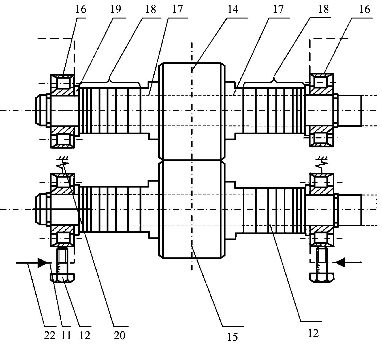
[0030] like Figure 4 shown, for figure 1 The test gear box control eccentric load adjustment schematic diagram; where: (a) before eccentric load adjustment; (b) after eccentric load adjustment; the specific eccentric load adjustment steps are as follows: when the eccentric load needs to be adjusted l , find the adjusting bushing 4-1 of the corresponding thickness. Before the gear is installed, the eight-tooth rectangular spline driven shaft is pulled out from the gearbox, and the adjusting bushing on the left side is moved to the position of the adjusting bushing on the right side of the shaft section. 4-3, and then complete the installation of the rest of the parts to achieve the partial load of t The eccentric load of the tooth surface is installed in 4-4.

Embodiment 2

[0031] Example 2: Testing Gearbox Misalignment Adjustment

[0032] like Figure 5 shown, for figure 1 The schematic diagram of the misalignment adjustment of the tested gearbox; where: (a) standard installation schematic diagram; (b) angular misalignment adjustment schematic diagram; (c) center distance error adjustment schematic diagram; the specific angular misalignment and center distance error adjustment steps are as follows: When it is necessary to adjust the misalignment of the gear angle, adjust the distance adjusting bolt on the left side alone (or adjust the distance adjusting bolt on the right side alone, and the left side does not move), the right side bolt remains still, and the effective shaft section length supported by the bearing is n , the length of the compressed spring on the left is m (see Figure 5-1), the length is obtained by observing the indicator cursor, then the angular misalignment at this time θ as (see Figure 5-2):

[0033] (1)

[0034] Fo...


PUM


Abstract

The invention discloses a gear fatigue testing machine considering gear misalignment and gear surface unbalanced loading. The gear fatigue testing machine is composed of a testing gear case (1), a torque clutch (3), an input shaft (4), a coupler (5), a motor (6), an accompanying gear case (10), and output shaft (8) and a loading clutch (9) through assembling; the gear fatigue testing machine controls misalignment and unbalanced loading of a gear pair in the gear case through a simple and easy mechanical apparatus so as to monitor a vibration signal of the gear case, is simple in structure, hasa wide range of application and can effectively complete experimental simulation of misalignment and unbalanced loading faults of different gear parameters.

Description

technical field [0001] The invention relates to a gear fatigue testing machine, in particular to a gear fatigue testing machine considering gear misalignment and tooth surface eccentric load. Background technique [0002] Gearboxes are one of the very important intermediate power transmission components in mechanical transmissions. Its main function is to change the rotation speed of the shaft, transmit torque and power split, etc. During the operation of the gearbox, due to the influence of tooth surface machining errors, alternating loads, or system installation errors, it is inevitable that the gearbox will have tooth surface peeling, pitting, gear installation misalignment, and tooth surface installation partial load, etc. The type of failure will cause the vibration and noise of the gearbox, thereby shortening the operating life of the gearbox gear, resulting in greater economic loss and casualties. Therefore, we can effectively predict through vibration signal monito...

Claims


Application Information

Patent Timeline
Patent Type & Authority Applications(China)
IPC IPC(8): G01M13/021
Inventor 马辉王昆曹海军吴宏登罗方陈康康皇甫一樊李娜
Owner JIANGSU JINXIANG TRANSMISSION EQUIP
Why Eureka
Try Eureka