Electric transmission line detection system, method and device
A transmission line and detection system technology, applied in the electrical field, can solve problems that have not yet been effectively solved, and achieve the effect of strong operability and key performance verification
- Summary
- Abstract
- Description
- Claims
- Application Information
AI Technical Summary
Problems solved by technology
Method used
Image
Examples
Embodiment 1
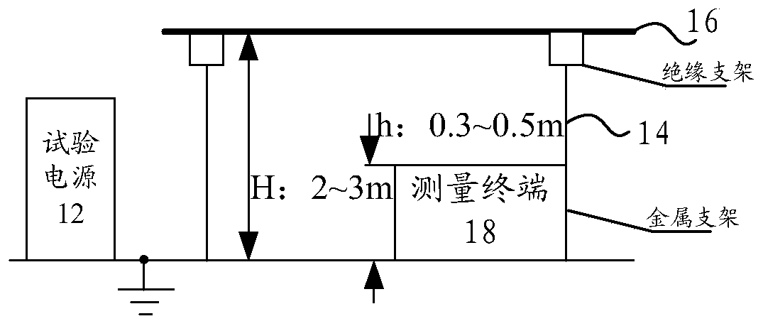
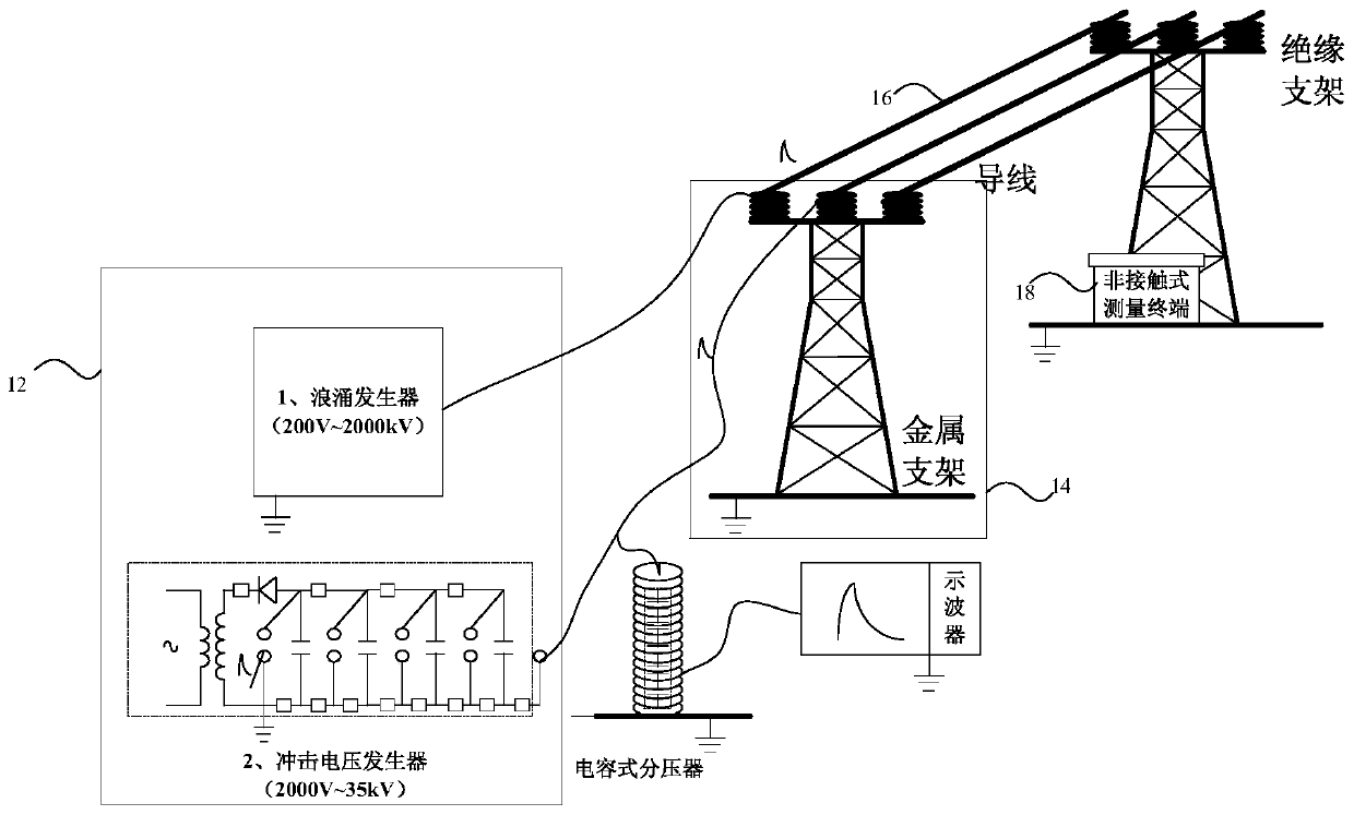
[0028] According to an aspect of an embodiment of the present invention, a power transmission line detection system is provided, figure 1 It is a schematic structural diagram of a transmission line detection system according to an embodiment of the present invention, including: a test power supply 12, a support 14, a wire 16 and a measurement terminal 18, wherein the test power supply 12 is used to output simulated traveling waves to the wire 16; the support 14 supports The wire 16 and the measurement terminal 18 are located below the wire 16 and close to the side of the support 14 for obtaining the monitored electric field state.
[0029] Specifically, the transmission line detection system provided by the embodiment of the present application uses a non-contact traveling wave device to monitor the change of the electromagnetic field under the same traveling wave current, and can analyze the resulting sudden change signal of the electric field without distortion.
[0030] Amo...
Embodiment 2
[0056] According to an embodiment of the present invention, an embodiment of a power transmission line detection method is provided. It should be noted that the steps shown in the flowcharts of the accompanying drawings can be executed in a computer system such as a set of computer-executable instructions, and, although A logical order is shown in the flowcharts, but in some cases the steps shown or described may be performed in an order different from that shown or described herein.
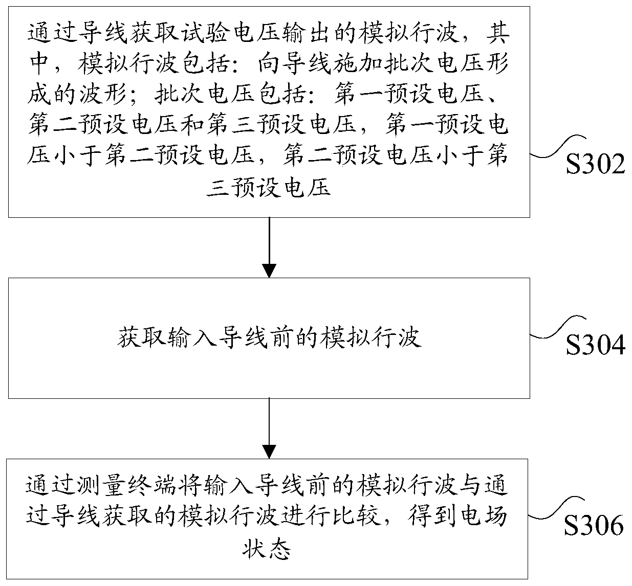
[0057] image 3 is a schematic diagram of a power transmission line detection method according to an embodiment of the present invention, such as image 3 As shown, the method includes the following steps:
[0058] Step S302, obtain the simulated traveling wave output by the test voltage through the wire, wherein the simulated traveling wave includes: a waveform formed by applying a batch voltage to the wire; the batch voltage includes: a first preset voltage, a second preset voltage and a thir...
Embodiment 3
[0065] According to still another aspect of the embodiments of the present invention, a power transmission line detection device is also provided, Figure 4 is a schematic structural diagram of a power transmission line detection device according to an embodiment of the present invention, such as Figure 4 shown, including:
[0066] The first obtaining module 42 is used to obtain the simulated traveling wave of the test voltage output through the wire, wherein the simulated traveling wave includes: a waveform formed by applying a batch voltage to the wire; the batch voltage includes: a first preset voltage, a second preset voltage Set the voltage and the third preset voltage, the first preset voltage is less than the second preset voltage, the second preset voltage is less than the third preset voltage; the second acquisition module 44 is used to acquire the analog traveling wave before the input wire; The detection module 46 is used to compare the analog traveling wave befor...
PUM
 Abstract
Description
Claims
Application Information
 - R&D
- Intellectual Property
- Life Sciences
- Materials
- Tech Scout
- Unparalleled Data Quality
- Higher Quality Content
- 60% Fewer Hallucinations
Browse by: Latest US Patents, China's latest patents, Technical Efficacy Thesaurus, Application Domain, Technology Topic, Popular Technical Reports.
© 2025 PatSnap. All rights reserved.Legal|Privacy policy|Modern Slavery Act Transparency Statement|Sitemap|About US| Contact US: help@patsnap.com


