An odometer motion estimation method based on binocular vision

A technology of motion estimation and binocular vision, applied in computing, image data processing, instruments, etc., can solve the problem of low robot pose accuracy, achieve the goal of improving pose accuracy, reducing calculation cost, and ensuring accuracy Effect

Pending Publication Date: 2019-05-10
HARBIN INST OF TECH
View PDF4 Cites 2 Cited by
  • Summary
  • Abstract
  • Description
  • Claims
  • Application Information

AI Technical Summary

Problems solved by technology

[0004] The purpose of the present invention is to solve the problem of low accuracy of robot pose obtained by existing methods, and propose a method for odometer motion estimation based on binocular vision

Method used


Image

  • An odometer motion estimation method based on binocular vision
  • An odometer motion estimation method based on binocular vision
  • An odometer motion estimation method based on binocular vision

Examples


specific Embodiment approach 1

[0033] Specific implementation mode one: the specific process of a binocular vision-based odometer motion estimation method in this implementation mode is as follows:

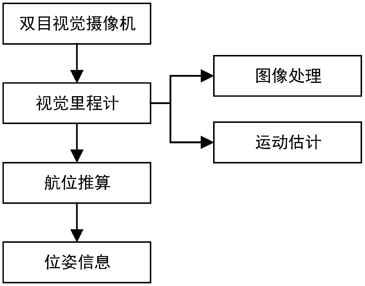
[0034] Such as figure 1 As shown, the specific content of the present invention is to rely on the binocular vision camera as the sensor, obtain the three-dimensional information of the scene feature points by processing the obtained image sequence, and then obtain the relative motion relationship of the mobile robot through the method of motion estimation, and then calculate the real-time position Posture information, the specific implementation process is as follows:

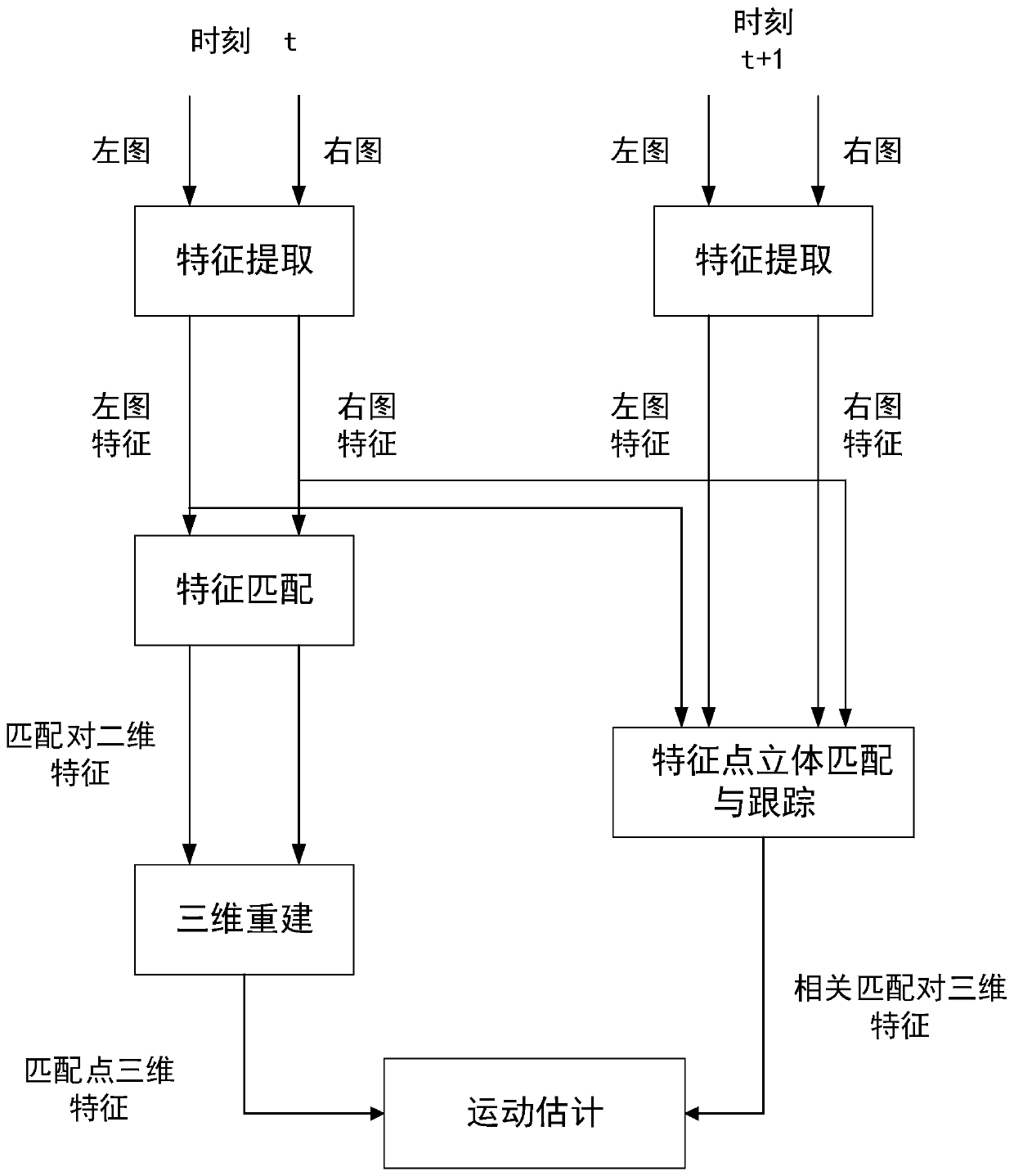
[0035] Step 1, such as figure 2 As shown, the binocular camera captures images of the current scene at the position of time t and the position of time t+1 respectively, and obtains the left image and right image collected by the binocular camera of the current scene at time t, and the binocular image at time t+1. The left image and right imag...

specific Embodiment approach 2

[0048] Specific embodiment two: the difference between this embodiment and specific embodiment one is that the method of Harris corner detection is adopted in the step 3 to extract the feature points of the image after the step 2 preprocessing, and the specific process is:

[0049] The Harris corner detection method is used to extract feature points from the left and right images preprocessed in step 2 respectively.

[0050] Other steps and parameters are the same as those in Embodiment 1.

specific Embodiment approach 3

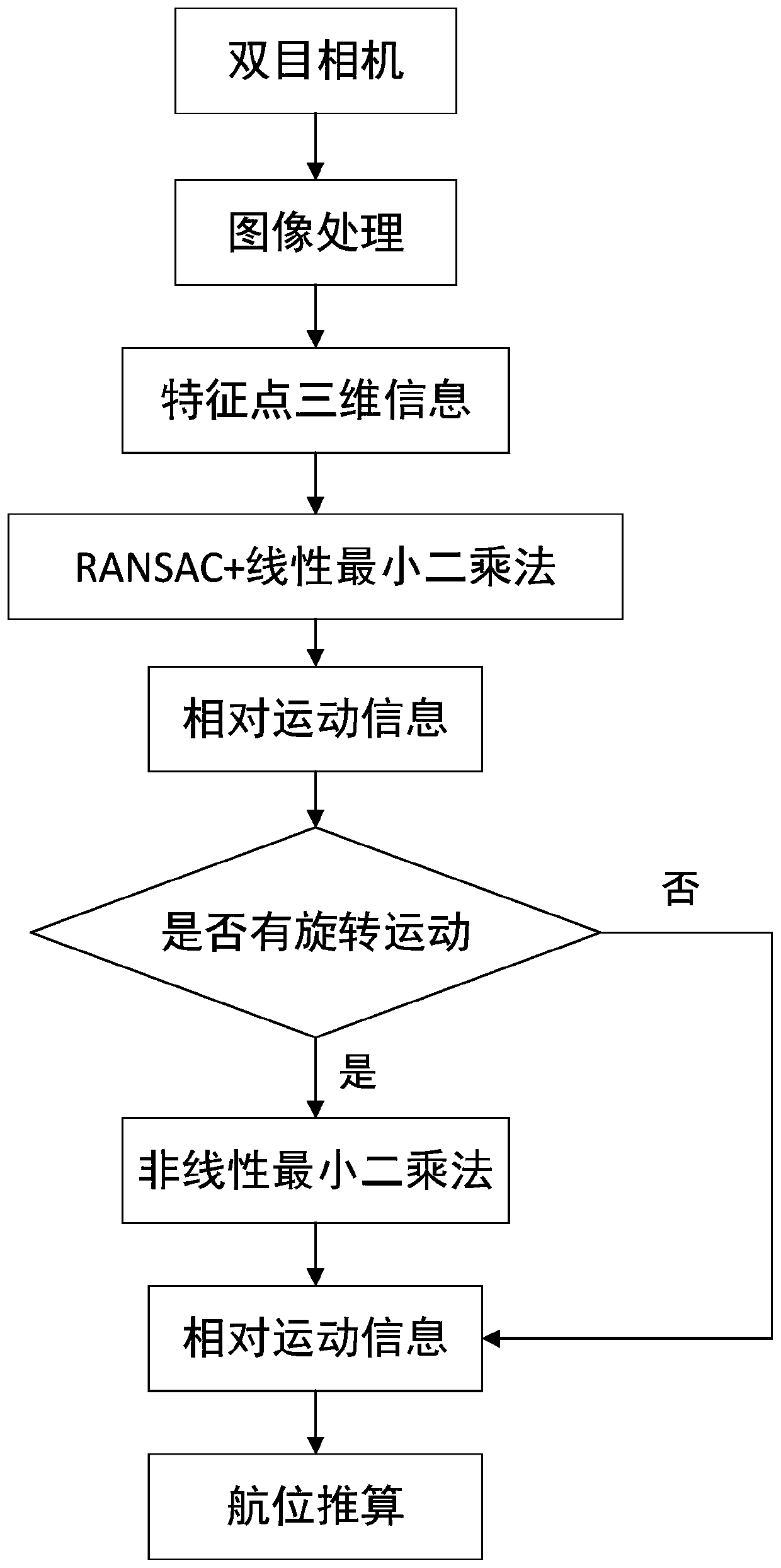
[0051] Embodiment 3: The difference between this embodiment and Embodiment 1 or 2 is that in Step 7, the three-dimensional information of the feature points obtained in Step 6 is used for motion estimation according to the motion estimation method; the specific process is:

[0052] Step 7-1. Use the improved RANSAC combined with the linear least squares method to process the three-dimensional information of the feature points obtained in step 6, and the motion parameters obtained are the final rotation matrix R end and translation matrix T end ;

[0053] Step 7-2. According to the final rotation matrix R end and translation matrix T end Obtain the relative rotation angle, and determine whether the relative rotation angle is greater than 3°;

[0054] Step 7-3. If the relative rotation angle is greater than 3°, use the linear least squares method to obtain the final rotation matrix R end and translation matrix T end Perform optimization, and the optimized result is used as ...


PUM


Abstract

The invention discloses an odometer motion estimation method based on binocular vision, and relates to an odometer motion estimation method based on binocular vision. The invention aims to solve the problem that the robot pose obtained by the existing method is low in accuracy. The method comprises the steps that 1, a binocular camera collects images of a current scene at the position of the moment t and the position of the moment t + 1; 2, preprocessing the acquired image; 3, extracting feature points from the preprocessed image; 4, matching the extracted feature points; 5, obtaining the three-dimensional information of the current scene feature point at the moment t and the three-dimensional information of the current scene feature point at the moment t + 1; 6, acquiring the three-dimensional information of the current scene feature point at the moment t and the three-dimensional information of the current scene feature point at the moment t + 1 which are successfully matched; and 7,performing motion estimation on the obtained three-dimensional information of the feature points according to a motion estimation method. The method is applied to the field of intelligent mobile robot autonomous navigation.

Description

technical field [0001] The invention relates to an odometer motion estimation method based on binocular vision. Background technique [0002] In the autonomous navigation of mobile robots, the pose information of the robot occupies a very important position, and accurate acquisition of the pose information of the robot is the basis for subsequent tasks. The traditional methods to obtain robot pose mainly include: traditional odometer based on wheel encoder, GPS and inertial navigation device. Among them, the traditional odometer based on the wheel encoder usually needs to calculate the number of wheel rotations or the rotational angular velocity to determine the vehicle speed. The biggest problem with this method is that it cannot overcome the counting or measurement errors caused by wheel slippage. Since the friction coefficient between the sports field and the wheels, the level of the ground, and the angle of inclination are usually not available, the occurrence and degre...

Claims


Application Information

Patent Timeline
Patent Type & Authority Applications(China)
IPC IPC(8): G06T7/285G06T7/246G06T7/73G06T7/13
Inventor 白成超郭继峰郑红星
Owner HARBIN INST OF TECH
Why Eureka
Try Eureka