
Novel girder type gas injection packing support

A technology of gas injection and packing support, applied in chemical/physical/physical-chemical process, chemical instrument and method, chemical/physical process, etc., can solve the problem of insignificant support strengthening effect, unfavorable liquid redistribution, liquid storage or particle accumulation and other problems, to achieve the effect of improving strength and stiffness, reducing deformation, and preventing aggregation

Pending Publication Date: 2019-05-14
PEI YANG NAT DISTILLATION TECH
View PDF1 Cites 0 Cited by
  • Summary
  • Abstract
  • Description
  • Claims
  • Application Information

AI Technical Summary

Problems solved by technology

[0004] The existing beam-type gas injection packing support is the hump support, such as patent CN204380690U, the left and right sides of the hump plate have upwardly folded connecting plates, and there are bolt holes on the top for the connection between the plates. The strengthening effect of the plate on the support is not obvious, and a large number of bolt connections not only increase the difficulty of installation but also increase the production cost
Moreover, the existence of this connecting plate hinders the flow of the bottom liquid on the hump plate on the one hand, which is not conducive to the redistribution of the liquid; on the other hand, the connecting plate easily makes the particulate matter in the liquid accumulate and adhere to it
For the hump support with an outer ring, the liquid coming down from the packing layer along the tower wall will accumulate between the outer ring and the inner wall of the tower, and it is not easy to flow out, and there may be liquid or particle accumulation.

Method used


Image

  • Novel girder type gas injection packing support
  • Novel girder type gas injection packing support
  • Novel girder type gas injection packing support

Examples


Embodiment Construction

[0024] The present invention will be further described in detail below in conjunction with the accompanying drawings and through specific embodiments. The following embodiments are only descriptive, not restrictive, and cannot limit the protection scope of the present invention.

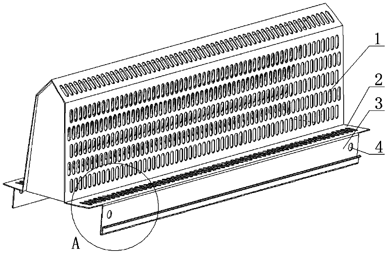
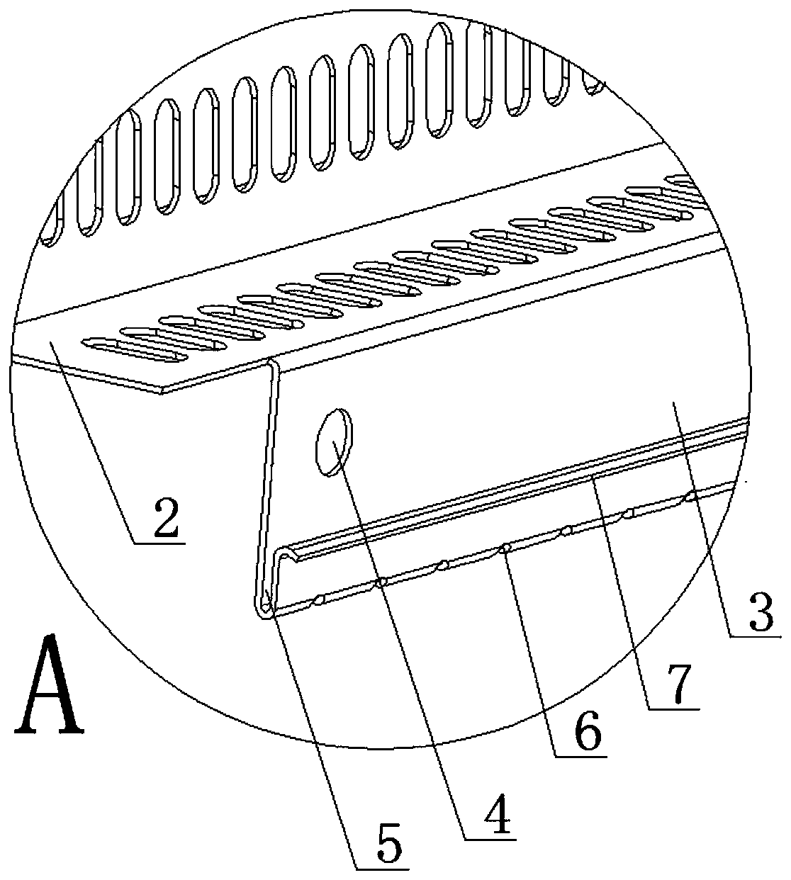
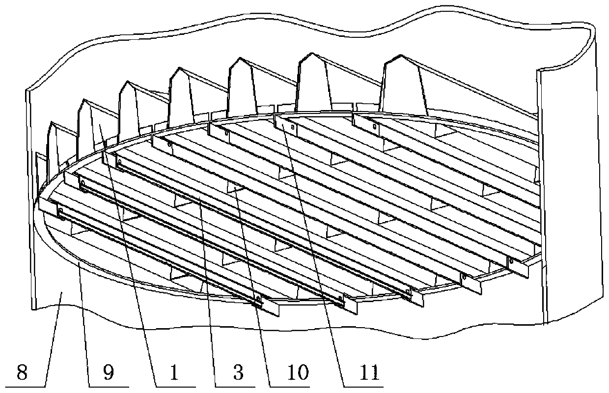
[0025] A new type of beam-type gas injection packing support unit, such as figure 1 , 2 As shown, it includes a hump plate 1, a support plate 2, and a connecting plate 3. The bottom of the hump plate is bent outwards along the horizontal direction to form a supporting plate, and the supporting plate is then bent downward to form a connecting plate. The connecting plate is perpendicular to the supporting plate. As required, the lower edge of the connecting plate is bent upward to form a slot 5 . In order to facilitate the liquid in the slot to flow out, a plurality of liquid guide holes 6 are evenly spaced at the bottom of the slot. In order to increase the strength of the slot, the upper edge of th...


PUM


Abstract

The invention relates to a novel girder type gas injection packing support, by changing the structure and the connecting mode of an existing hump bearing plate, the strength and the rigidity of a support structure are substantially improved on one side, and particularly for a large-tower-diameter high-packing-layer random packing tower, the height of a main girder is effectively reduced, the material is further saved, the space is saved, and the height of a tower body is reduced on a certain degree. On the other side, the novel girder type gas injection packing support gets rid of a connectingbolt between hump plates, but an inserted connection structure is adopted, a large quantity of bolts are saved while the processing and the mounting are simple and convenient, and the production costis lowered; moreover, the novel girder type gas injection packing support enables a liquid between an edge ring and a tower wall to flow out smoothly, the flowing barrier of the liquid flowing between the hump bearing plates is removed, the transverse flowing of the liquid is benefited, the liquid on a bottom plate is more evenly distributed, and the mass transfer efficiency of the tower is further improved.

Description

technical field [0001] The invention belongs to the field of chemical industry and relates to tower internals in chemical packing towers, in particular to a novel beam-shaped gas injection packing support applied to large random packing towers. Background technique [0002] In the petrochemical process production process, the packed tower is a commonly used chemical unit equipment, which uses the packing in the tower as a mass transfer device between the gas-liquid two-phase contact member. The packed tower has the advantages of large production capacity, high separation efficiency, small pressure drop, small liquid holdup, and large operating flexibility. [0003] In recent years, due to the continuous improvement of the packing structure, a series of new high-efficiency, high-load structured packing and random packing have been developed, which not only improves the passing capacity and separation efficiency of the tower, but also maintains the characteristics of small pre...

Claims


Application Information

Patent Timeline
Patent Type & Authority Applications(China)
IPC IPC(8): B01J19/30B01J19/32
Inventor 田琳静彭鹄许力强宋娜郭利新
Owner PEI YANG NAT DISTILLATION TECH
Learn More