Intelligent vehicle light eye system

A smart car and optical eye technology, which is applied to vehicle components, optical observation devices, transportation and packaging, etc., can solve the problems of long liability identification period, driver's blindness, and endangering the driver's personal safety, so as to reduce the occurrence of traffic accidents , Improving the driving safety level, the effect of improving the driving safety level

Inactive Publication Date: 2019-05-14
吉林省洪科光电技术有限公司
View PDF4 Cites 2 Cited by
  • Summary
  • Abstract
  • Description
  • Claims
  • Application Information

AI Technical Summary

Problems solved by technology

[0002] At present, traditional motor vehicle headlights generally use xenon lamp lighting to improve the visual range, but due to the high illuminance of the lights, it will cause temporary blindness to the oncoming pedestrians and vehicle drivers, which brings extreme damage to pedestrians and drivers. In addition, the traditional xenon headlights cannot provide a visual effective distance within a safe distance under low visibility weather conditions, resulting in some traffic accidents such as rear-end collisions due to insufficient braking distance, which endangers the driver's personal safety , and some traditional motor vehicle traffic accidents require the traffic police or insurance companies to go to the scene to collect evidence, and then judge and deal with it through surrounding video surveillance. The responsibility identification cycle is long, which affects the driver's normal driving plan
[0003] In addition, the existing intelligent unmanned vehicles all use vehicle-mounted radar, but because the radar has blind spots and is easily affected by the weather, and the lidar is expensive, the safe driving ability of the current intelligent unmanned vehicles has not reached the real level. application requirements

Method used


Image

  • Intelligent vehicle light eye system
  • Intelligent vehicle light eye system
  • Intelligent vehicle light eye system

Examples


Embodiment Construction

[0018] In order to make the purpose, technical solution and advantages of the present invention more clear, the present invention will be further described in detail below in conjunction with the accompanying drawings and embodiments. It should be understood that the specific embodiments described here are only used to explain the present invention, not to limit the present invention.

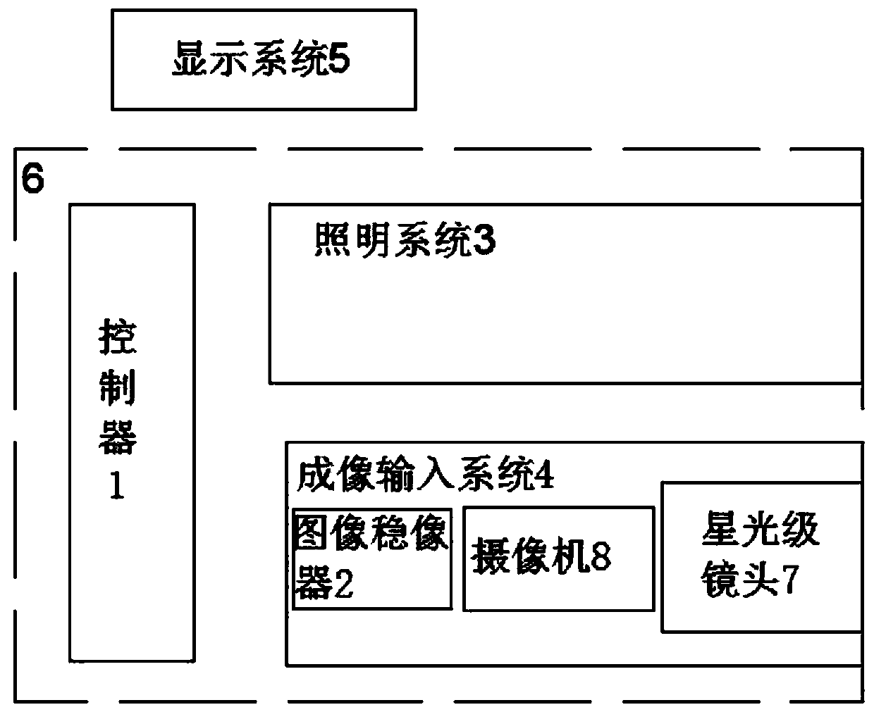
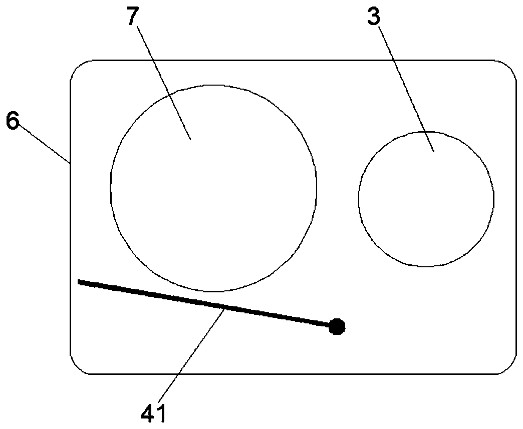
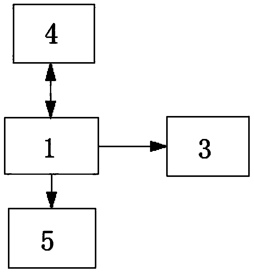
[0019] refer to Figure 1 to Figure 6 , including a protective cover 6 and a display system 5 for displaying images on the windshield glass or display screen in the cab, the protective cover 6 is provided with a controller 1, a lighting system 3 and an imaging input system 4; the control The device 1 is electrically connected with the lighting system 3, the imaging input system 4 and the display system 5 respectively; the lighting system 3 includes an infrared band semiconductor laser array 31, an infrared zoom lens 32 and a zoom motor 33; the imaging input system 4 includes Image Stabilizer 2...


PUM


Abstract

The invention relates to an intelligent vehicle light system. The intelligent vehicle light eye system includes a protective cover and a display system. The protective cover is internally provided with a controller, an illuminating system and an imaging input system; the controller is electrically connected with the illuminating system, the imaging input system and the display system; the illuminating system includes an infrared band semiconductor laser array group, an infrared zoom lens and a zoom motor; and the imaging input system includes an image stabilizing device, a camera and a star-level lens. According to the intelligent vehicle light eye system, the capacities of beyond-visual-range star-level imaging and storing record can be obtained under the light with a low illumination level, an existing method of headlight illuminating can be replaced, vehicle outside environment imaging is displayed in real-time, thus a driver in a cab is provided with clear real-time road conditionvideo image aided driving, the dead zone problem that a vehicle radar can be prone to being effected by weather can be made up, and further development of driverless technology is promoted.

Description

technical field [0001] The invention relates to the field of automobiles, in particular to an intelligent automobile optical eye system. Background technique [0002] At present, traditional motor vehicle headlights generally use xenon lamp lighting to improve the visual range, but due to the high illuminance of the lights, it will cause temporary blindness to the oncoming pedestrians and vehicle drivers, which brings extreme damage to pedestrians and drivers. In addition, the traditional xenon headlights cannot provide a visual effective distance within a safe distance under low visibility weather conditions, resulting in some traffic accidents such as rear-end collisions due to insufficient braking distance, which endangers the driver's personal safety , and some traditional motor vehicle traffic accidents require traffic police or insurance companies to go to the scene to collect evidence, and then judge and deal with it through peripheral video surveillance. The responsi...

Claims


Application Information

Patent Timeline
Patent Type & Authority Applications(China)
IPC IPC(8): B60R1/00
Inventor 杨洪武赵英伟宋硙
Owner 吉林省洪科光电技术有限公司
Why Eureka
Try Eureka