A vehicle and a control power system thereof

A power system and vehicle control technology, applied in the field of vehicle power system, can solve the problems of high cost and complicated layout of the whole vehicle, and achieve the effects of cost reduction, avoiding loss of main force, and efficient use of energy.

Inactive Publication Date: 2019-05-14
ZHENGZHOU YUTONG BUS CO LTD
8 Cites 1 Cited by

AI-Extracted Technical Summary

Problems solved by technology

[0003] The purpose of the present invention is to provide a vehicle and its control power system, which is used to solve the problem of cumber...

Method used

(1) Since the whole vehicle needs power steering at all times, the steering oil pump 7 is directly connected to the motor shaft of the accessory drive motor 9, and works synchronously with the accessory drive motor 9. That is, the steering oil pump 7 is directly connected to the accessory drive motor 9 through the reserved bearing of the motor, and the connection structure can be connected by a flexible coupling to reduce vibration and noise and reduce impact. The steering oil pump and accessory drive motor have a 1:1 speed ratio. The steering pump pressure and displacement parameters are designed according to the requirements of the vehicle steering gear. The displacement is secondly designed with reference to the rotation speed range of the accessory drive motor to ensure that the pressure and flow of the steering pump meet the steering power requirements of the vehicle. need.
The accessory drive motor of the present invention can drive five electric accessories of steering oil pump, air compressor, air-conditioning compressor, cooling water pump, low-voltage generator simultaneously, can realize centralized arrangement, is conducive to the integration of vehicle accessories and reduces the Cost; and according to the type of electric accessories, determine the specific control method, and use the total output of the motor near the rated power to realize centralized control and improve the efficiency and energy utilization of the motor. In addition, each electric accessory breaks through the traditional engine drive structure, and is driven by another independent accessory motor (...

Abstract

The invention relates to a vehicle and a control power system thereof. The control power system comprises a whole vehicle control motor used for driving a whole vehicle to operate, an accessory driving motor, electric accessories, and an accessory driving motor controller that is connected with a whole vehicle controller and in control connection with the accessory driving motor; the accessory driving motor is in transmission connection with the electric accessories, and the electric accessory comprises at least two of a low-voltage generator, an air compressor, an air conditioner compressor and a cooling water pump. According to the system, one accessory driving motor and the corresponding accessory motor controller are independently adopted to drive a plurality of vehicle electric accessories, i.e., the plurality of electric accessories share one accessory driving motor and one controller, which is beneficial to the integrated arrangement of the whole vehicle, the cost reduction andthe high-efficiency utilization of energy.

Application Domain

Speed controllerFluid steering +2

Technology Topic

Air compressorElectric machine +4

Image

  • A vehicle and a control power system thereof
  • A vehicle and a control power system thereof

Examples

  • Experimental program(1)

Example Embodiment

[0019] In order to make the objectives, technical solutions and advantages of the present invention clearer, the present invention will be further described in detail below with reference to the accompanying drawings and specific embodiments.
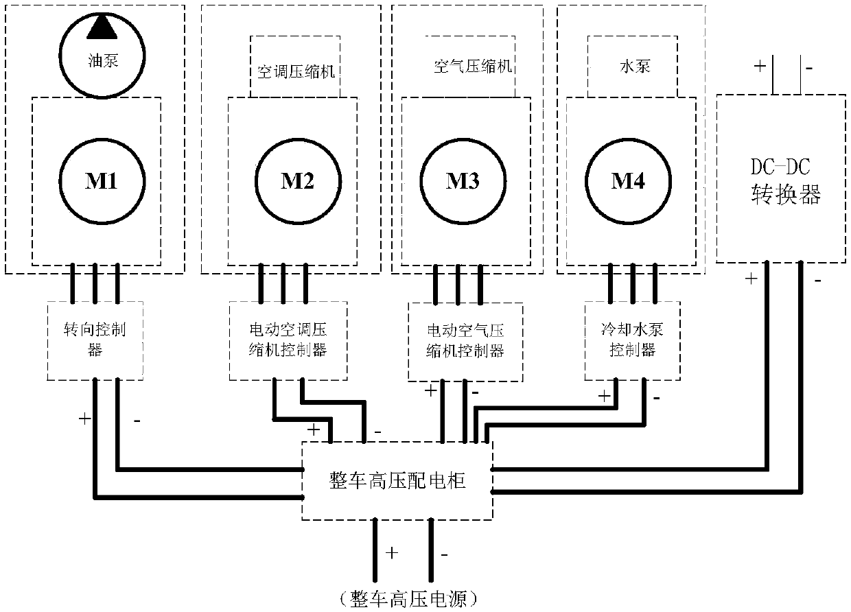
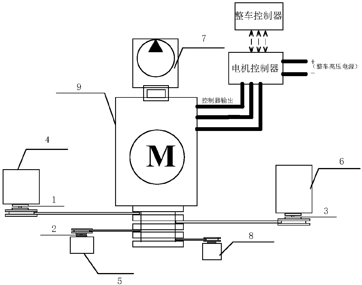
[0020] The present invention provides a vehicle. The type of the vehicle is not limited, and can be a large-load vehicle such as an electric electric passenger car, an electric truck, an electric logistics vehicle, an electric sweeper, and an electric commercial vehicle. The vehicle includes a vehicle controller and a vehicle control power system. like figure 2 As shown, the vehicle control power system includes a vehicle control motor, an accessory drive motor, an electric accessory, and an accessory drive motor controller. The vehicle controller controls the connection accessory drive motor controller, the accessory drive motor controller controls the connection accessory drive motor, and the accessory drive motor drives the connection electric accessory.
[0021] Specifically, the above-mentioned vehicle control motor, that is, the main drive motor, is used to drive the vehicle to run and provide power for the vehicle to run. The accessory drive motor 9 is a multifunctional motor. In this embodiment, a permanent magnet synchronous motor is used. The permanent magnet synchronous motor has the advantages of high efficiency, fast response, low noise, strong overload capacity, and relatively small volume and weight compared with other types of motors. Power density and other advantages. The accessory drive motor controller is a controller matched to the permanent magnet synchronous motor. Of course, as other implementation manners, the accessory drive motor may also adopt other types of multifunctional motors in the prior art, and in this case, the accessory drive motor controller is correspondingly changed. The accessory drive motor controller is powered by the vehicle's high-voltage power supply, and is controlled by the vehicle's entire controller, maintaining communication with the vehicle's control at any time.
[0022] The electric accessories include an air-conditioning compressor 4, a cooling water pump 5, an air compressor 6, a steering oil pump 7 and a low-voltage generator 8, and the above-mentioned five electric accessories are driven by the accessory drive motor at the same time. The specific drive connection methods are as follows:
[0023] (1) Since the whole vehicle needs steering assistance at all times, the steering oil pump 7 is directly connected to the motor shaft of the accessory drive motor 9 and works synchronously with the accessory drive motor 9 . That is, the steering oil pump 7 is directly connected to the accessory drive motor 9 through the bearing reserved by the motor, and the connection structure can be connected by a flexible coupling to reduce vibration and noise and reduce impact. The steering oil pump and the accessory drive motor have a 1:1 speed ratio. The pressure and displacement parameters of the steering pump are designed according to the needs of the steering gear of the vehicle. The displacement is secondly designed with reference to the speed range design of the accessory drive motor to ensure that the pressure and flow of the steering pump meet the steering assist of the vehicle. need.
[0024] (2) Since the low-voltage generator 8 needs to supplement the vehicle battery and the low-voltage power demand of the vehicle at any time, the low-voltage generator is directly connected to the accessory drive motor 9 through the belt, and works with the accessory drive motor 9 at the same time. As long as the accessory drive motor 9 works, the low-voltage generator generates power for the entire vehicle, and is stored in the battery for use by the low-voltage electrical appliances of the entire vehicle. The transmission speed ratio between the accessory drive motor and the low-voltage generator is designed according to the actual situation.
[0025] Of course, as other implementations, the low-voltage generator can also be connected to the accessory drive motor by a key transmission or gear transmission or other transmission methods.
[0026] (3) The air-conditioning compressor 4, the cooling water pump 5, and the air compressor 6 start to work only when certain conditions are met. Therefore, the first electromagnetic clutch 1, the second electromagnetic clutch 2 and the third electromagnetic clutch 3 are used for the three electric accessories respectively. Connect, meet the starting conditions, the electromagnetic clutch is engaged, and the corresponding accessory assembly starts to work. When the electromagnetic clutch is disconnected, the accessory assembly stops working. The air conditioner control switch controls the connection of the first electromagnetic clutch 1 ; the vehicle controller controls the connection of the second electromagnetic clutch 2 and the third electromagnetic clutch 3 .
[0027] The electromagnetic clutches used by the three electric accessories of the air-conditioning compressor 4, the cooling water pump 5, and the air compressor 6 are currently mature components and can be directly applied to the vehicle control power system. In this embodiment, the electromagnetic clutch adopts a multi-friction plate electromagnetic clutch, which controls the coupling and separation of the clutch by controlling the on and off of the coil, and adopts a normally open form, that is, the power is turned on and the power is turned off. The torque is transmitted through the friction plate, which can be sucked or separated at high speed. It can be a coupling type or a flange type. The three electromagnetic clutches are of different specifications according to the different loads when the air conditioner compressor, cooling water pump and air compressor are switched in.
[0028] For the air conditioner compressor, the corresponding first electromagnetic clutch 1 is turned on and off by the air conditioner button A/C controller on the instrument panel. When the driver presses the A/C button, the electromagnetic clutch 1 is closed, and the air conditioner compressor starts to work. The operator turns off the A/C button, the electromagnetic clutch 1 is disconnected, and the air conditioner compressor stops working. The transmission speed ratio between the accessory drive motor and the air conditioner compressor is designed according to the actual situation.
[0029] For the cooling water pump, when the temperature signal transmitted by the temperature sensor of the object to be cooled (main drive motor or other controllers, etc.) to the vehicle controller satisfies the cooling water pump startup condition (higher than the starting temperature), the vehicle controller controls the first The second electromagnetic clutch 2 is closed. The cooling water pump starts to work, when the temperature is lower than the lower limit, the second electromagnetic clutch 2 is disconnected, and the cooling water pump stops working. The transmission speed ratio between the accessory drive motor and the cooling water pump is designed according to the actual situation.
[0030] For the air compressor, its structure is as follows: the air path of the air compressor is directly connected to the dryer (where the air pressure sensor is installed), the four-circuit air valve, and then divided into four paths into the front and rear brake air storage tanks, respectively. The parking air tank, the auxiliary air tank, and the third electromagnetic clutch 3 signal come from the start-stop signal given by the vehicle controller, and the vehicle controller gives the start-stop switch signal based on the air pressure sensor signal. The air pressure sensing signal inside the dryer is transmitted to the vehicle controller, and the vehicle controller controls the third electromagnetic clutch 3 to be turned on and off. That is, when the air pressure is lower than the lower limit, the electromagnetic clutch 3 is closed, the air compressor is connected, and the whole vehicle starts to be pumped. When the air pressure meets the upper limit, the electromagnetic clutch 3 is disconnected and stops pumping. The transmission speed ratio between the accessory drive motor and the air compressor is designed according to the actual situation.
[0031]The accessory drive motor of the present invention can simultaneously drive five electric accessories of a steering oil pump, an air compressor, an air conditioner compressor, a cooling water pump, and a low-voltage generator, and can realize centralized arrangement, which is beneficial to the integration of the accessories of the whole vehicle and reduce the cost of the whole vehicle; and According to the type of electric accessories, the specific control method is determined. By using the total output of the motor near the rated power, centralized control can be achieved, which improves the motor efficiency and energy utilization. In addition, each electric accessory breaks through the traditional engine drive structure, and uses another independent accessory motor (instead of the main drive motor, and does not participate in the vehicle drive) to drive, that is, the power drive structure of the electric accessories is designed separately and is not shared with the main drive. , Each electric accessory designs the corresponding connection structure according to its working principle, each electric accessory rarely works at the same time under the maximum load, the vehicle control is more secure, and the optimal control can be achieved, which is not only conducive to the best work of each accessory area, and the vehicle is comfortable and light to operate.

PUM

no PUM

Description & Claims & Application Information

We can also present the details of the Description, Claims and Application information to help users get a comprehensive understanding of the technical details of the patent, such as background art, summary of invention, brief description of drawings, description of embodiments, and other original content. On the other hand, users can also determine the specific scope of protection of the technology through the list of claims; as well as understand the changes in the life cycle of the technology with the presentation of the patent timeline. Login to view more.

Similar technology patents

Apparatus and method for low-density cellular wood plastic composites

InactiveUS20050067729A1less-expensivelow cost
Owner:STRANDEX CORP

Haptic trackball device

InactiveUS7710399B2simple actuatorlow cost
Owner:IMMERSION CORPORATION

Steering Arrangement for a Trailer

InactiveUS20110018231A1low cost
Owner:ZF FRIEDRICHSHAFEN AG

Classification and recommendation of technical efficacy words

  • efficient use of energy
  • low cost

Energy-saving system of excavator

ActiveCN105971053AHigh transmission efficiencyefficient use of energy
Owner:XCMG EXCAVATOR MACHINERY

Steam generating method for preparing liquid air

InactiveCN104764293Aefficient use of energy
Owner:宁波高新区零零七工业设计有限公司

System and method for transmitting wireless digital service signals via power transmission lines

ActiveUS7929940B1reduce bandwidth requirementlow cost
Owner:NEXTEL COMMUNICATIONS

System and method for determination of position

InactiveUS20090149202A1low costreduce requirement
Owner:STEELE CHRISTIAN

Adaptive antenna optimization network

InactiveUS6961368B2low costminimal space
Owner:ERICSSON INC

Antenna device and method for attaching the same

ActiveUS20150138022A1low costimproved strength characteristic
Owner:NEC CORP
Why Eureka
Try Eureka