
Wind turbine blade ice prevention and removal mechanism

A wind turbine blade and control technology, applied in wind turbines, machines/engines, engines, etc., can solve the problems of waste heat loss, increased manufacturing cost, complex structure, etc.

Inactive Publication Date: 2019-05-14
NORTHEAST AGRICULTURAL UNIVERSITY
View PDF6 Cites 7 Cited by
  • Summary
  • Abstract
  • Description
  • Claims
  • Application Information

AI Technical Summary

Problems solved by technology

Therefore, in order to ensure the normal operation of the wind turbine, it is necessary to add a set of devices for cooling the generator and the gearbox in the wind turbine system, which has complex structure, increased manufacturing cost, and especially the loss and waste of heat energy.

Method used


Image

  • Wind turbine blade ice prevention and removal mechanism

Examples


Embodiment Construction

[0011] Embodiments of the present invention will be described in detail below in conjunction with the accompanying drawings.

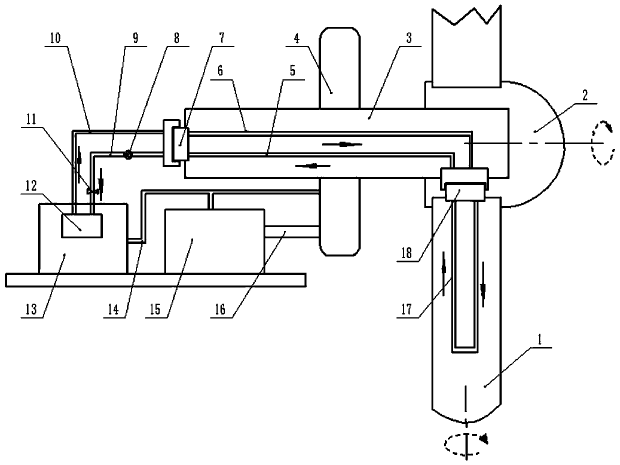
[0012] A wind turbine blade anti-icing mechanism, the main shaft 3 is rotatably fitted on the gear transmission box 4, and is connected with the gear transmission box 4, the hub 2 is fixed on the front end of the main shaft 3, and the gear transmission box 4 passes through the transmission shaft 16 Connected with the generator 15, the blade 1 is rotatably fitted on the hub 2 through the rotary joint B18, and the condenser 17 is installed in the blade 1, and the inlet end and the outlet end of the condenser 17 are respectively connected with the rotary joint The rotary end of B18 is fixedly connected; the rotary joint A7 is installed on the rear end of the main shaft 3, the steam delivery pipe B6 and the liquid return pipe A5 are arranged in the shaft cavity of the main shaft 3, and the steam inlet and outlet ends of the steam delivery pipe B6 Connect w...


PUM


Abstract

Disclosed is a wind turbine blade ice prevention and removal mechanism belonging to ice prevention and removal technology. A hub is provided with a blade through a rotary joint B. A condenser is installed in the blade. Two ends of the condenser are respectively connected with the rotary joint B. A rotary joint A is installed on the rear end portion of a main shaft. A steam transfer pipe B and a liquid return pipe A are arranged in a shaft cavity of the main shaft. Two ends of the steam transfer pipe B are connected with the rotary joint A and the rotary joint B correspondingly. Two ends of theliquid return pipe A are connected with the rotary joint B and the rotary joint A correspondingly. A gear transmission box and a generator communicate with a heat accumulator through heat transfer pipes. An evaporator is installed in the heat accumulator. Two ends of the steam transfer pipe A are connected to the evaporator and the rotary joint A correspondingly. Two ends of a liquid return pipeB are connected to the rotary joint A and the evaporator correspondingly. A liquid pump and a valve are installed on the liquid return pipe B. The wind turbine blade ice prevention and removal mechanism uses waste heat energy generated by a wind turbine to carry out blade ice prevention and removal, thereby saving energy and being low in operation cost and good in operation effect.

Description

technical field [0001] The invention belongs to the anti-icing technology and mainly relates to an anti-icing mechanism used on wind turbine blades. Background technique [0002] When a wind turbine operates under atmospheric conditions containing supercooled water droplets, icing will occur on the blades. Icing will affect the aerodynamic characteristics of the blades, resulting in a reduction in the output power of the wind turbine, and even shutting down the wind turbine. Changes in the load will affect the structural strength and fatigue life of the wind turbine, resulting in safety accidents. When the wind turbine is adjacent to roads, houses and transportation lines, the large icicles falling off the blades of the wind turbine will pose a serious threat to engineering service personnel and nearby residents. Additionally, icing can affect the reliability of anemometers, producing inaccurate wind speed measurements. [0003] At present, domestic and foreign research on...

Claims


Application Information

Patent Timeline
Patent Type & Authority Applications(China)
IPC IPC(8): F03D80/40F03D80/60
CPCY02E10/72
Inventor 李岩李晓娟许智冯放
Owner NORTHEAST AGRICULTURAL UNIVERSITY
Learn More