OLED flexible laminating device and laminating process thereof

A flexible bonding and bonding technology, which is applied in the manufacture of electrical components, electrical solid devices, semiconductor/solid devices, etc., can solve the problems of reducing bonding air bubbles, FILM diaphragm position offset, and easy occurrence of air bubbles, etc., to prevent Effect of detachment, reduction of bonding air bubbles, and improvement of bonding quality

Pending Publication Date: 2019-05-14
SHENZHEN ETMADE AUTOMATION EQUIP
View PDF0 Cites 1 Cited by
  • Summary
  • Abstract
  • Description
  • Claims
  • Application Information

AI Technical Summary

Problems solved by technology

During the manufacturing process of the OLED display, it is necessary to attach a FILM film which is also flexible on its surface; and when the OLED film and the FILM film are supplied, the surface is attached with a protective film body, and the FILM film and the OLED film need to be separated before attaching the FILM film and the OLED film. After tearing off the surface of the OLED diaphragm and the film body on the bottom surface of the FILM diaphragm, the two are then bonded together; in the process of automatically pasting the FILM film on the OLED diaphragm, the following key technical problems need to be solved: 1. FILM diaphragm One side of the FPC is mostly connected to the FPC. During the transfer and bonding process of the FILM diaphragm, affected by the gravity of the FPC itself, the FPC hangs down and bends to the FILM tearing film platform or the OLED diaphragm, causing the FILM diaphragm to be damaged and easily affected. FILM placement or bonding; therefore, it is necessary to design an auxiliary holding structure for the FPC of the FILM diaphragm to ensure that it does not hang and bend during its handling and bonding; 2. The two bonding planes of the FILM diaphragm and the OLED diaphr

Method used


Image

  • OLED flexible laminating device and laminating process thereof
  • OLED flexible laminating device and laminating process thereof
  • OLED flexible laminating device and laminating process thereof

Examples


Example Embodiment

[0034] The present invention will be further described below in conjunction with the accompanying drawings:

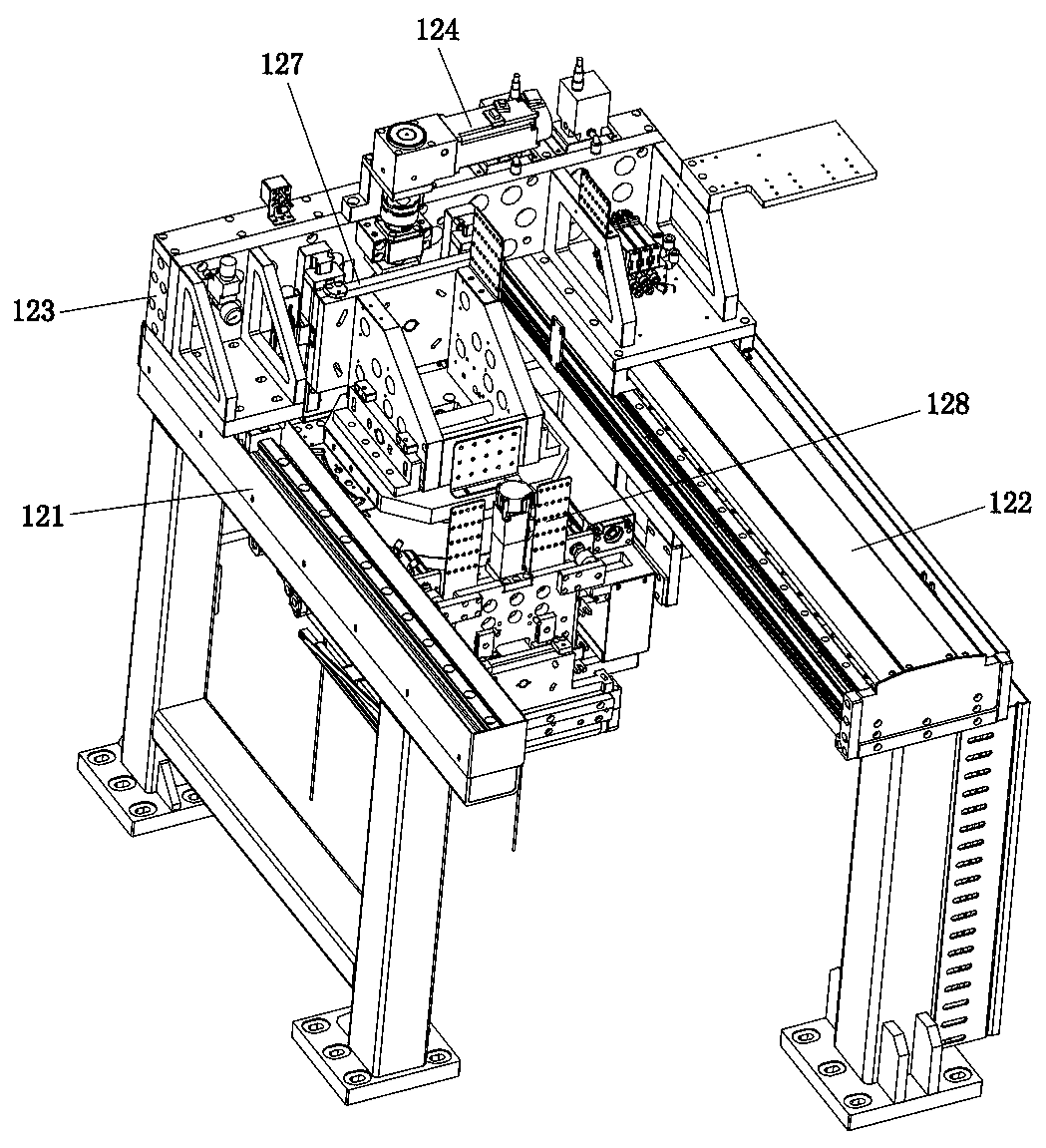
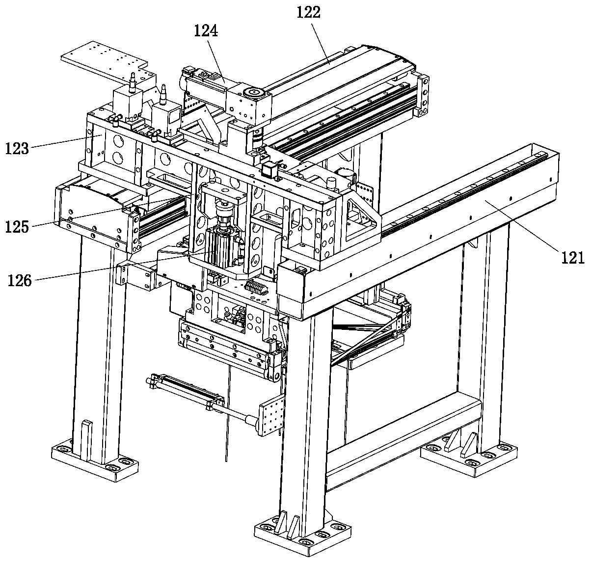
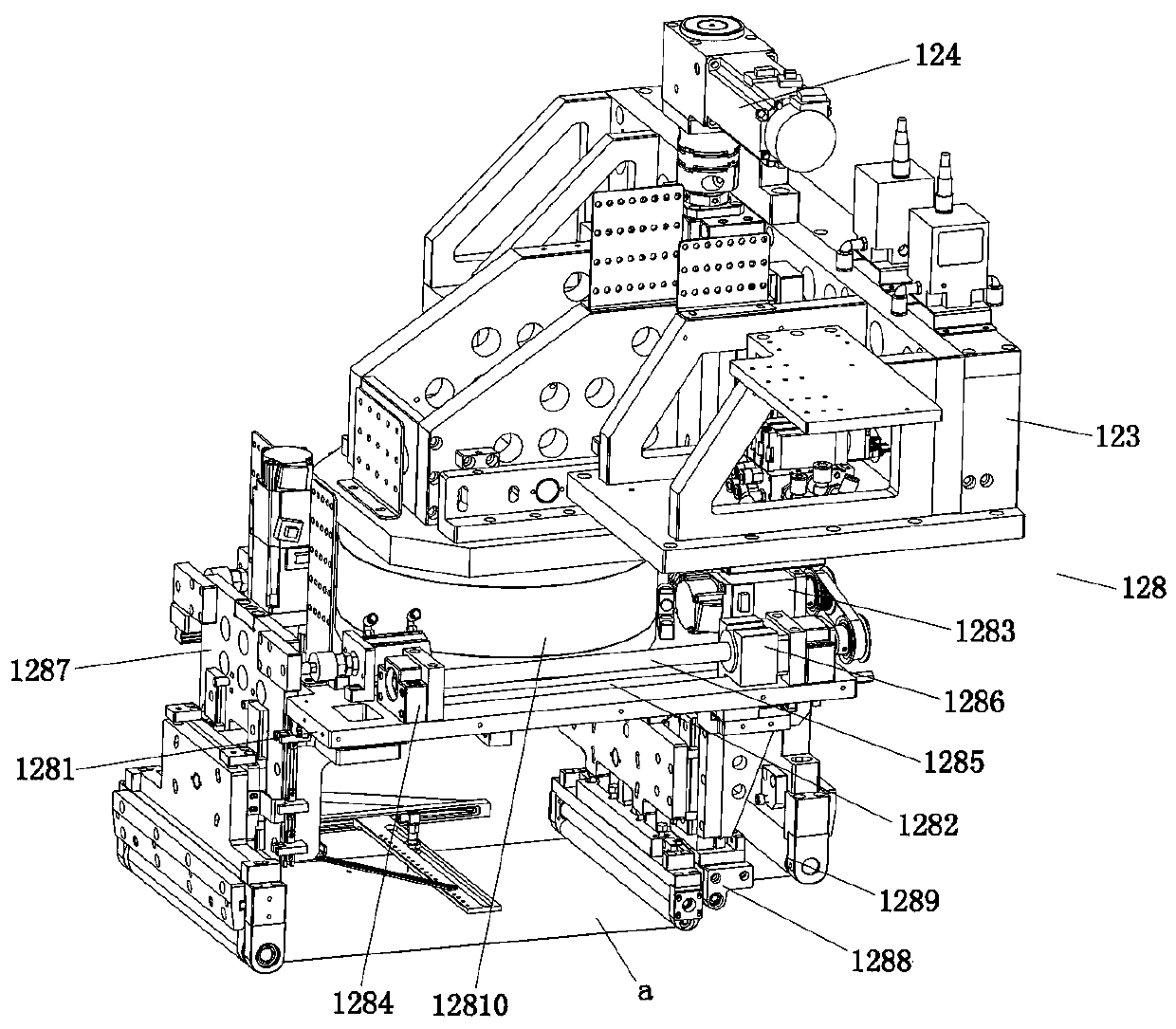
[0035] Such as Figure 1 to Figure 10 As shown, the technical solution adopted by the present invention is as follows: An OLED flexible laminating device is set in a soft-to-soft laminating machine, and moves the FILM film to the soft-to-soft laminating machine by adhering the film after the tearing is completed After taking pictures at the CCD mechanism of the machine and aligning the FILM film, the FILM film is continuously bonded to the OLED film; including the bonding bracket 121, the bonding linear module 122, the bonding linear slide 123, and the bonding The fitting lifting motor 124, the fitting mounting seat 125, the fitting weight reduction cylinder 126, the fitting lifting seat 127 and the fitting head 128, wherein the fitting bracket 121 is arranged at the rear end of the frame, and the fitting bracket 121 includes parallel Two frame bodies are arranged at int...


PUM


Abstract

The invention discloses an OLED flexible laminating device and a laminating process thereof. The device comprises a laminating bracket, a laminating linear module, a laminating linear sliding seat, alaminating lifting motor, a laminating mounting seat, a laminating weight elimination cylinder, a laminating lifting seat and a laminating head, wherein the laminating bracket is arranged at the rearend of a frame; the laminating linear module is arranged on the upper part of the laminating bracket; the laminating linear sliding seat is arranged on the laminating linear module along the directionperpendicular to the laminating linear module; the laminating lifting motor is arranged on the upper part of the laminating linear sliding seat; the laminating mounting seat is arranged on the otherside of the laminating linear sliding seat, the laminating weight elimination cylinder is arranged in the laminating mounting seat, and the output end is connected with the laminating head; and the laminating lifting seat is slidably arranged on the side wall at one side of the laminating linear sliding seat. According to the scheme of the invention, the height difference forms at the two ends ofan adhesive film strip, so that the FILM membrane and an OLED membrane are in linear contact, laminating bubbles are effectively reduced, and the angle change during lamination of the FILM membrane iscontrolled through the up-down adjustable film pressing roller, so that the separation of the FILM membrane can be prevented.

Description

technical field [0001] The invention relates to the field of automatic manufacturing, in particular to an OLED flexible bonding device and a bonding process thereof. Background technique [0002] An OLED display is a display made of organic electroluminescent diodes. Since it also has self-luminous organic electroluminescent diodes, no backlight is required, high contrast, thin thickness, wide viewing angle, fast response speed, can be used for flexible panels, wide operating temperature range, simple structure and manufacturing process, etc. , is considered to be the next-generation flat-panel display emerging application technology. OLED is a self-luminous material that does not need a backlight panel. At the same time, it has a wide viewing angle, uniform image quality, fast response speed, easy colorization, light emission can be achieved with a simple driving circuit, simple manufacturing process, and can be made into a flexible panel. In line with the principle of li...

Claims


Application Information

Patent Timeline
IPC IPC(8): H01L51/56H01L27/32
Inventor 高军鹏
Owner SHENZHEN ETMADE AUTOMATION EQUIP
Why Eureka
Try Eureka