Coordinated fault ride-through method for large-scale offshore wind power transmission via flexible DC
A technology of offshore wind power and flexible direct current, applied in wind power generation, single grid parallel feeding arrangement, etc., can solve the problems of ineffective realization of large-scale offshore wind power coordinated fault ride-through, and achieve coordinated fault ride-through, size reduction, and improved dynamics The effect of recovery properties
- Summary
- Abstract
- Description
- Claims
- Application Information
AI Technical Summary
Problems solved by technology
Method used
Image
Examples
specific Embodiment approach 1
[0050] Specific implementation mode 1: The coordinated fault ride-through method for large-scale offshore wind power transmission through flexible direct current described in this implementation mode, the method is:
[0051] During the fault period, the sending-end system cooperates with the voltage-active current reduction control of the wind turbine through the segmental step-down control (PVDC) to reduce the step-down depth of the grid-connected point of the wind farm;
[0052] After the fault is cleared, the sending end system realizes the adaptive restoration of the MMC-HVDC DC voltage and the output active power of the wind farm through the adaptive boost control (AVRC) and the voltage-active current rise control of the wind turbine.
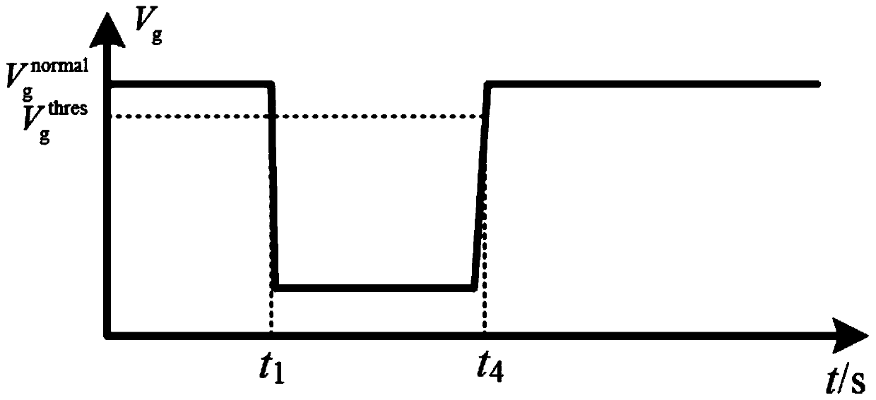
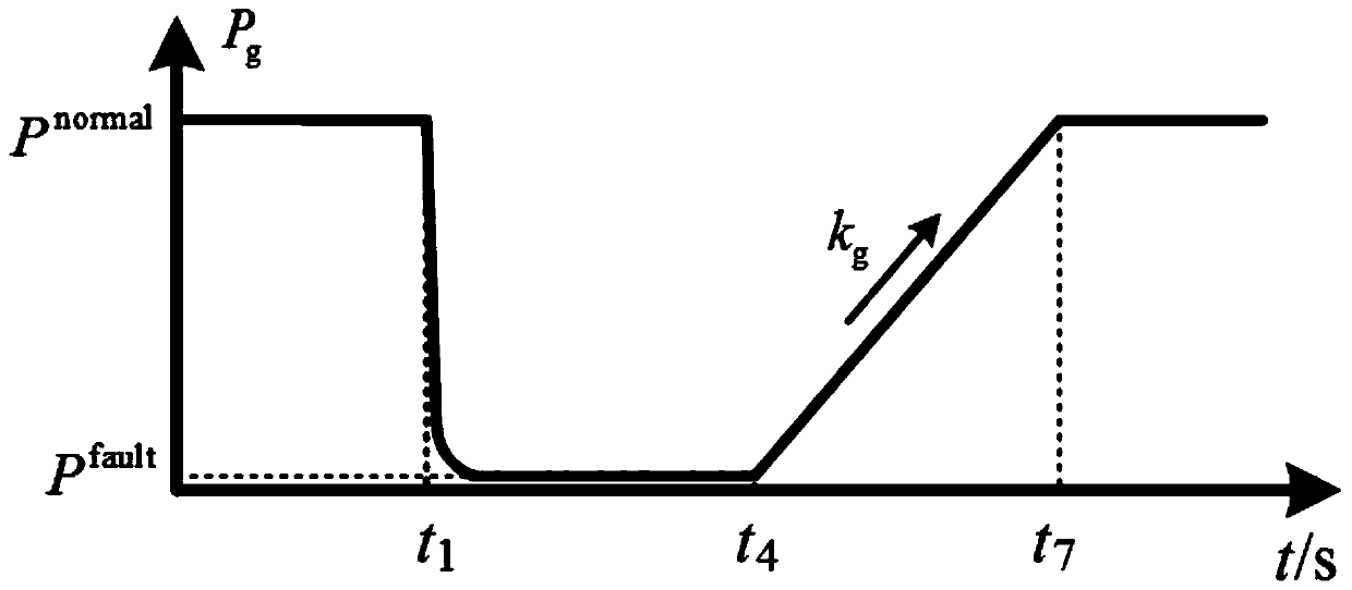
[0053] Depend on figure 2 , image 3 , Image 6 shown, t 1 A three-phase short-circuit fault occurs in the power grid at any time, and GSMMC detects the AC voltage V of the GSMMC grid-connected point g drops to its action threshold ...
specific Embodiment approach 2
[0057] Embodiment 2: This embodiment differs from Embodiment 1 in that: the step-down voltage reduction control improves the voltage reduction rate and load shedding efficiency by combining the forced voltage reduction control and the droop control.
[0058] PVDC cooperates with the voltage-active current reduction control (VDACR) of wind turbines to reduce the maximum step-down depth of the wind farm, prevent the frequency instability of the sending end system, and suppress the The DC voltage overshoot improves the safety of the DC system operation, and the V w Reduce ΔV w , to compensate for the adverse effects of system control response delay. . The adaptive voltage boosting scheme (AVRC) cooperates with the voltage-active current rise control (VDACI) of the wind turbine to realize the adaptive recovery of the DC voltage and wind power, improve the dynamic recovery characteristics of the DC voltage, and realize the DC system from the FRT mode to the steady state. The smo...
specific Embodiment approach 3
[0059] Specific implementation mode three: the difference between this implementation mode and specific implementation mode two is: if Figure 7 As shown, the specific process of the forced step-down control is:
[0060] like Figure 8 and 9 As shown, after the step-down control starts, (that is, t 2 time ), regardless of the severity of the fault and the steady-state power level of the wind farm, the grid-connected voltage of the wind farm (WFMMC) immediately decreases by ΔV w , ΔV w called the transient voltage drop, given by Figure 10 It can be seen that ΔV w The expression is:
[0061]
[0062] In the formula, and are the DC voltage thresholds corresponding to the start and exit of step-down control, K FRT is the proportional coefficient of step-down control;
[0063] Proportional coefficient K of step-down control FRT The expression is:
[0064]
[0065] is the grid-connected voltage of the wind farm during normal operation of the system; is the...
PUM
 Abstract
Description
Claims
Application Information
 - R&D
- Intellectual Property
- Life Sciences
- Materials
- Tech Scout
- Unparalleled Data Quality
- Higher Quality Content
- 60% Fewer Hallucinations
Browse by: Latest US Patents, China's latest patents, Technical Efficacy Thesaurus, Application Domain, Technology Topic, Popular Technical Reports.
© 2025 PatSnap. All rights reserved.Legal|Privacy policy|Modern Slavery Act Transparency Statement|Sitemap|About US| Contact US: help@patsnap.com


