Electric push rod

An electric push rod and push rod technology, which is applied in the direction of electric components, electrical components, electromechanical devices, etc., can solve the problem that the push rod mechanism cannot accurately control the stroke, and achieve the effects of easy replacement, increased stability, and stroke control.

Pending Publication Date: 2019-05-14
浙江百缔传动科技有限公司
View PDF1 Cites 5 Cited by
  • Summary
  • Abstract
  • Description
  • Claims
  • Application Information

AI Technical Summary

Problems solved by technology

[0003] The purpose of the present invention is to solve the problem that the push rod mechanism i

Method used


Image

  • Electric push rod
  • Electric push rod
  • Electric push rod

Examples


Embodiment Construction

[0021] The following will clearly and completely describe the technical solutions in the embodiments of the present invention with reference to the accompanying drawings in the embodiments of the present invention. Obviously, the described embodiments are only some, not all, embodiments of the present invention.

[0022] In describing the present invention, it should be understood that the terms "upper", "lower", "front", "rear", "left", "right", "top", "bottom", "inner", " The orientation or positional relationship indicated by "outside", etc. is based on the orientation or positional relationship shown in the drawings, and is only for the convenience of describing the present invention and simplifying the description, rather than indicating or implying that the referred device or element must have a specific orientation, so as to Specific orientation configurations and operations, therefore, are not to be construed as limitations on the invention.

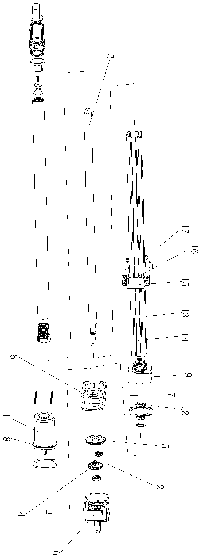
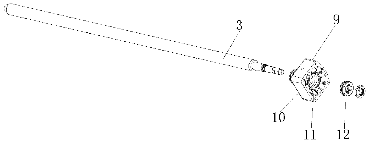
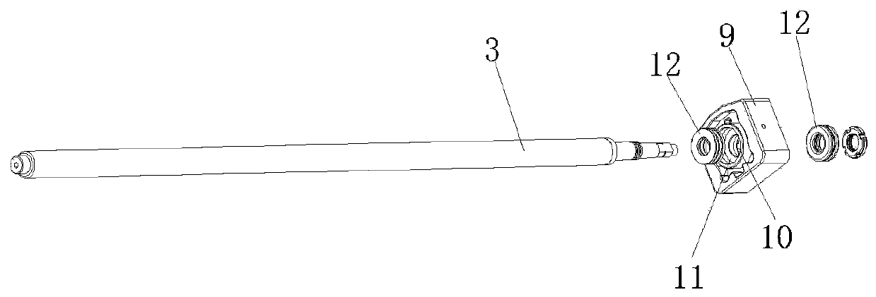
[0023] see Figure 1-3 ,...


PUM


Abstract

The invention discloses an electric push rod. The electric push rod comprises a DC motor, a transmission mechanism and a push rod, wherein the transmission mechanism comprises a main gear in axis connection with the DC motor and a transmission gear connected with the push rod, a plurality of wheel speed sensors are uniformly arranged on the transmission gear at interval, a signal receiver is arranged below the transmission gear, the signal receiver is connected with a controller, the controller controls and is connected with the DC motor, and the wheel speed sensors, the signal receiver and the controller coordinate with each other so as to control the DC motor and further control rotation turns and rotation angle of the transmission gear, thereby enabling the push rod to produce accurateaxial movement stroke. The wheel speed sensors and the signal receiver coordinate so as to calculate rotation turns of the transmission gear, when the transmission gear rotates to the desired turns, the controller controls the DC motor to start or stop.

Description

technical field [0001] The invention relates to the technical field of mechanical equipment, in particular to an electric push rod. Background technique [0002] At present, Chinese patent literature discloses a motor push rod, application publication number (CN 207796016 U), which includes a drive mechanism, a transmission mechanism and a push rod mechanism, the output end of the drive mechanism is connected to the input end of the transmission mechanism, and the The output end of the transmission mechanism is connected to the input end of the push rod mechanism, and it is characterized in that: the input end of the push rod mechanism is a gear clutch mechanism. The connected lead screw is provided with an outer tube outside the lead screw, a travel switch connected to the drive mechanism is arranged inside the outer tube, and an inner tube is also arranged on the lead screw, and the inner tube and the The lead screw is connected by a nut, the inner tube is driven by the l...

Claims


Application Information

Patent Timeline
IPC IPC(8): H02K7/06H02K11/215
Inventor 章之望崔大奎
Owner 浙江百缔传动科技有限公司
Why Eureka
Try Eureka