Supercharge Your Innovation With Domain-Expert AI Agents!

Slag discharging hole structure of vertical-mill grinding disc

A technology of slag discharge holes and grinding discs, which is applied in the direction of grain processing, etc., can solve the problems of reducing the number of grinding times, increasing the release and discharge probability of metal iron, and the difficulty of separating metal iron, so as to achieve the effect of prolonging the service life

Pending Publication Date: 2019-05-17
LOESCHE (SHANGHAI) CO LTD
View PDF0 Cites 0 Cited by
  • Summary
  • Abstract
  • Description
  • Claims
  • Application Information

AI Technical Summary

Problems solved by technology

[0004] The purpose of the present invention is to solve the technical problem that the above-mentioned existing materials with high iron content and high iron content are difficult to get rid of the grinding table of the vertical mill, aiming at the characteristics of high hardness and high iron content of steel slag materials, combined with the characteristics that iron particles cannot be ground and broken, to provide A vertical mill disc slag discharge hole structure, matched with a material retaining ring of appropriate height, can separate and discharge iron components in time, reducing the enrichment of metallic iron on the grinding disc; at the same time, it improves the yield of single grinding and reduces the The number of grinding increases the release and discharge probability of metal iron in steel slag, effectively solves the problem that metal iron in steel slag is not easy to separate, realizes the re-entry of the external circulation material after iron removal, reduces the wear of grinding disc and roller, and improves the grinding efficiency. efficiency

Method used


Image

  • Slag discharging hole structure of vertical-mill grinding disc
  • Slag discharging hole structure of vertical-mill grinding disc

Examples


Embodiment

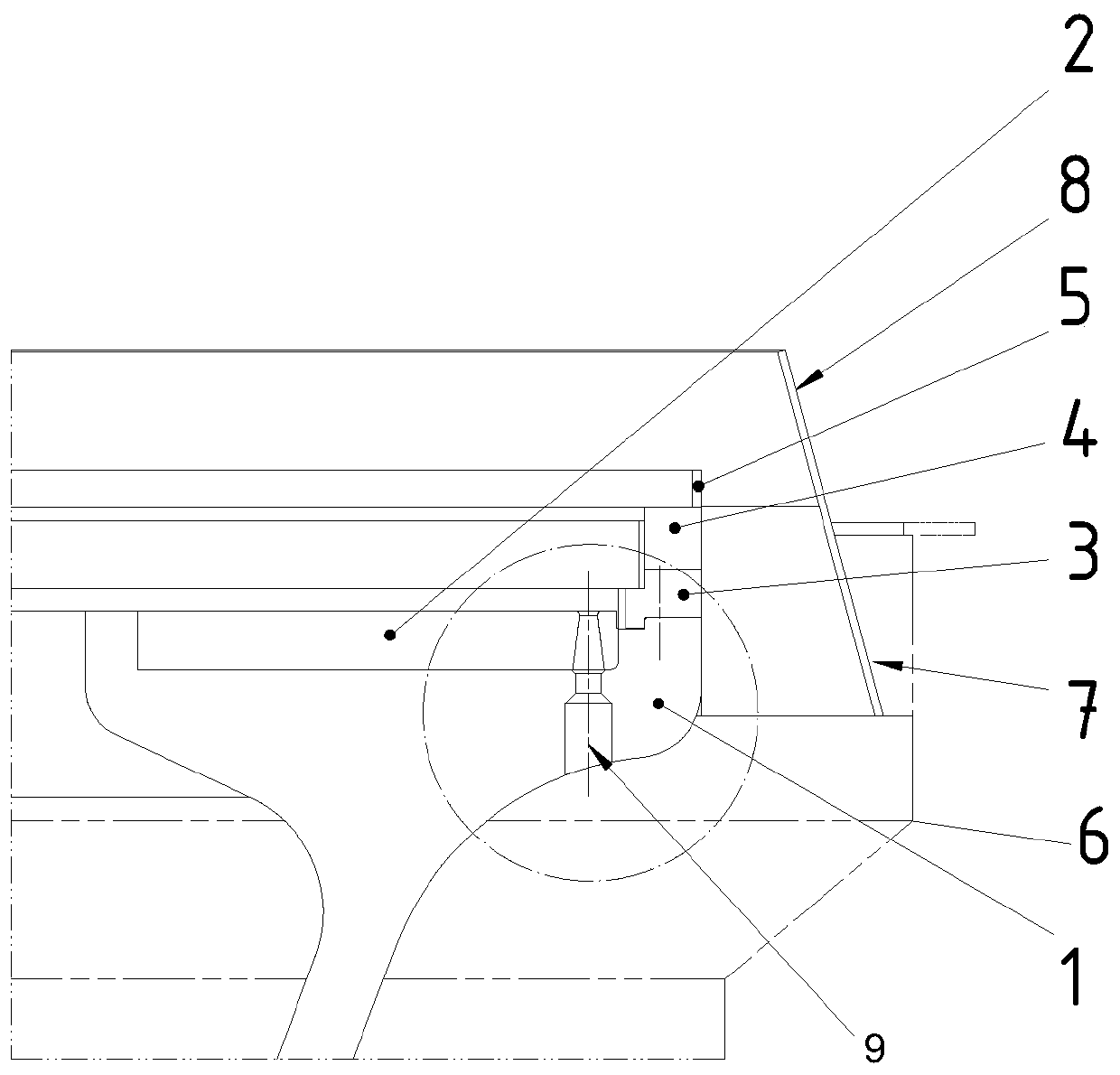
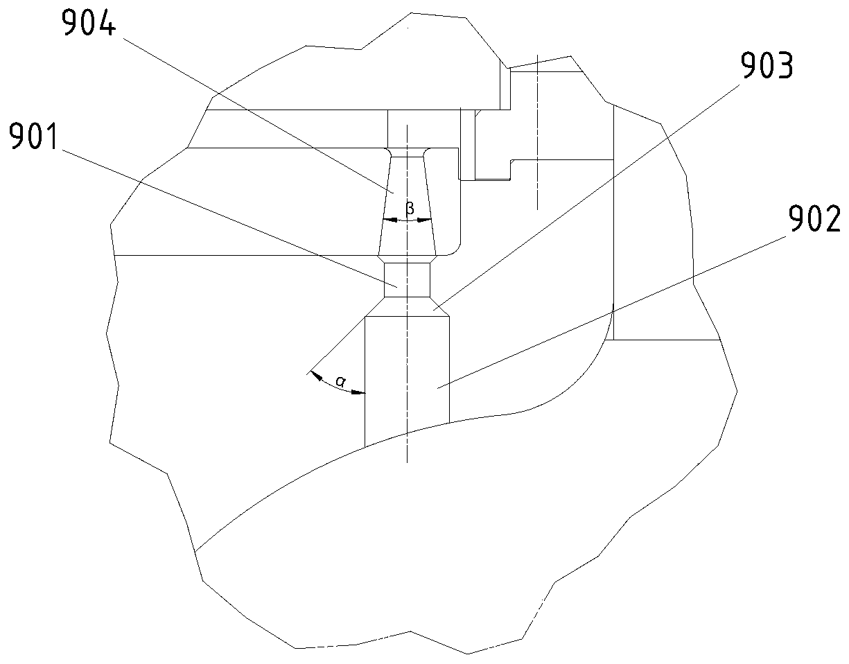
[0017] as attached figure 1 and 2 As shown, a vertical mill grinding disc slag discharge hole structure, which includes a grinding disc 1, a grinding disc liner 2 is installed on the grinding disc 1, a stopper base 3 is installed at the edge of the grinder 1, and the stopper base 3 The upper surface is fixed with a retaining ring 4, and the upper surface of the retaining ring 4 is fixed with a bulk material ring 5. An air ring 7 is arranged between the mill shell 6 and the grinding disc 1, and the upper end of the air ring 7 is connected with a The wear-resistant ring 8 is characterized in that: the edge of the grinding disc 1 and the grinding disc liner 2 is provided with a through slagging hole 9, and the slagging hole 9 is connected with the material retaining base 3, the material retaining ring 4 and the bulk material Neither ring 5 will intersect. The size of the slag discharge hole 9 must be determined according to the flow area, direction and flow velocity of the wind...


PUM

PropertyMeasurementUnit
Taperaaaaaaaaaa
Taperaaaaaaaaaa

Abstract

The invention discloses a slag discharging hole structure of a vertical-mill grinding disc. The slag discharging hole structure of the vertical-mill grinding disc comprises the grinding disc (1), a grinding disc liner plate (2) is arranged on the grinding disc (1), a material blocking base body (3) is arranged at the edge of the grinding disc (1), a material blocking ring (4) is fixedly arranged on the material blocking base body (3), a material separating ring (5) is fixedly arranged on the upper surface of the material blocking ring (4), an air ring (7) is arranged between a grinding machineshell (6) and the grinding disc (1), and a wear-resistant ring (8) is connected to the top of the air ring (7). The slag discharging hole structure of the vertical-mill grinding disc is characterizedin that the edges of the grinding disc (1) and the grinding disc liner plate (2) are provided with a through slag discharging hole (9), and the slag discharging hole (9) do not intersect with the material blocking base body (3), the material blocking ring (4) and the material separating ring (5). When a vertical mill grinds steel slags or similar materials whose content of hard-to-grind components is relatively high, the vertical-mill grinding disc makes the iron particles in the grinding process move towards the edge of the grinding disc liner plate under the action of centrifugal force, andfall into a circular air channel below the grinding disc to be discharged out of the mill under the action of a scraping plate, and therefore the service life of the grinding disc liner plate and a grinding roller sleeve are prolonged.

Description

technical field [0001] The present invention relates to material grinding equipment, in particular to a vertical mill used for grinding various materials in metal ore, non-metallic ore, energy, new materials and other industries, especially a vertical mill grinding disc row that can facilitate the removal of materials from the grinding disc Slag hole structure. Background technique [0002] The vertical mill is a grinding equipment that integrates drying, grinding, powder selection, and transportation. Ultrafine material grinding. The vertical mill has been invented for more than a century. The grinding process of the vertical mill is completed by a set of grinding devices (that is, rollers and discs), and the materials are ground between the rollers and the discs. into a powder. The kinetic energy of the grinding device is driven by the rotation of the grinding disc to drive the grinding roller to rotate. In addition to the self-weight of the grinding roller, the grindin...

Claims


Application Information

Patent Timeline
IPC IPC(8): B02C15/00
Inventor 黄涛
Owner LOESCHE (SHANGHAI) CO LTD
Features
  • R&D
  • Intellectual Property
  • Life Sciences
  • Materials
  • Tech Scout
  • Unparalleled Data Quality
  • Higher Quality Content
  • 60% Fewer Hallucinations
Learn More