Rubber bushing vulcanization mold

A technology of vulcanization molds and rubber bushings, applied in the field of vulcanization molds, can solve problems such as reducing production efficiency, difficult to seal rubber, and molds cannot be held down, so as to improve quality and pass rate, solve surface quality problems, and facilitate opening. The effect of mold pickup

Active Publication Date: 2019-05-17
NINGBO TUOPU GROUP CO LTD
View PDF10 Cites 3 Cited by
  • Summary
  • Abstract
  • Description
  • Claims
  • Application Information

AI Technical Summary

Problems solved by technology

For the rubber bushing vulcanization mold with this structure, although the rubber-sealed ribs are also designed at the intersection of the upper mold insert and the inner tube, due to the high hardness of the inner tube (up to HRC40-42) and too hard The mold cannot press the inner tube, and it is easy to wear the mold, and the upper end surface of the inner tube is equipped with 0.5mm deep teeth, and because the rubber is pervasive, it is difficult to seal the rubber, and the rubber is easy to enter during the injection process. in the bore of the inner tube
In this way, during the vulcanization process, the inner tube and the upper template are easy to get stuck or hang on the upper template when the mold is opened. Even if the product is opened and taken out, there are many waste edges, and the finished product needs to be repaired, which reduces the production efficiency.

Method used


Image

  • Rubber bushing vulcanization mold
  • Rubber bushing vulcanization mold
  • Rubber bushing vulcanization mold

Examples


Embodiment 1

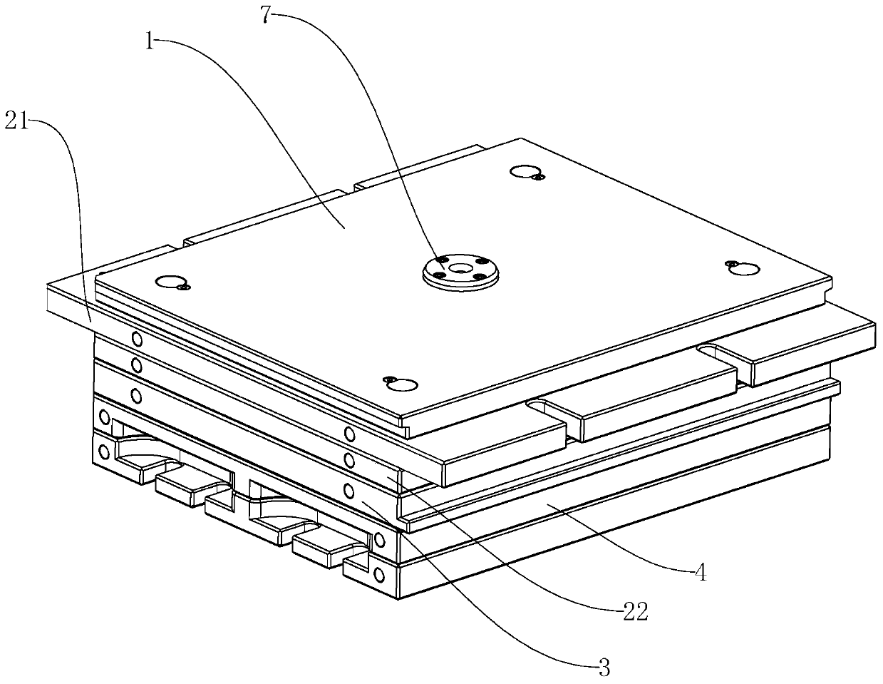
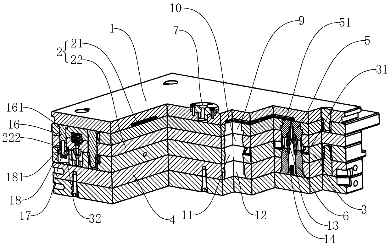
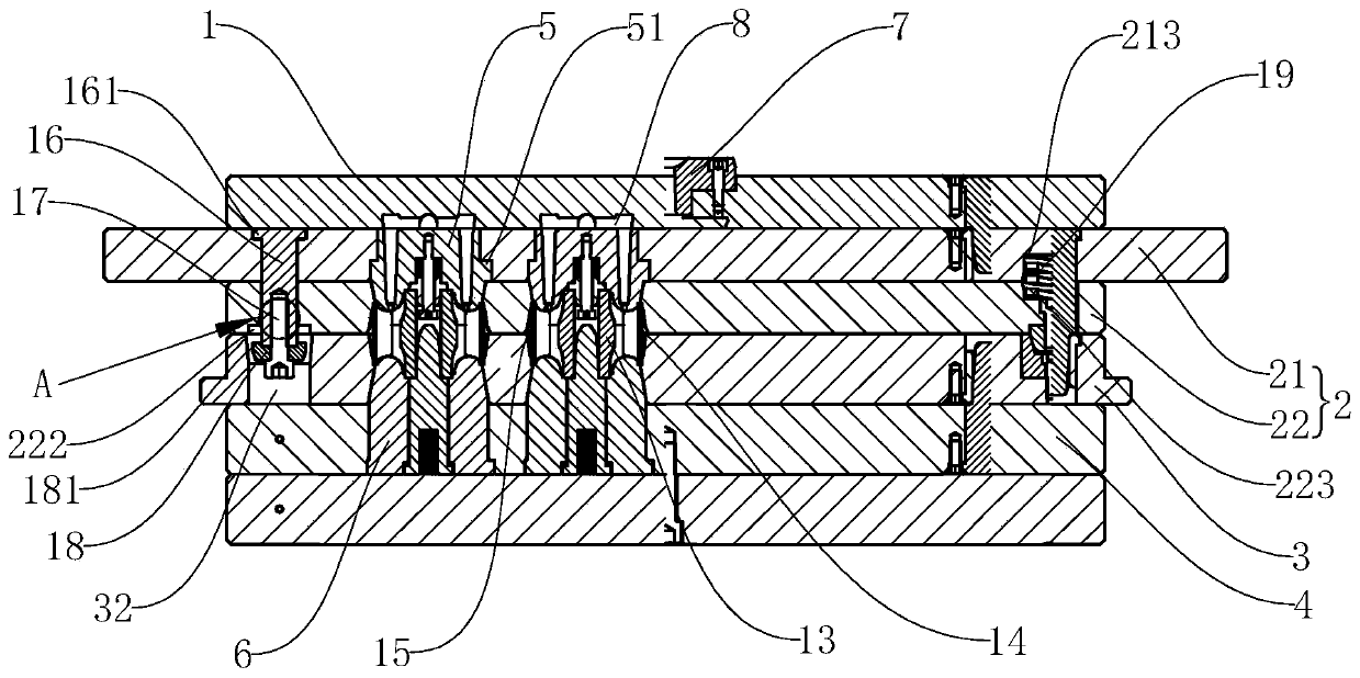
[0033]Embodiment 1: As shown in the figure, a rubber bush vulcanization mold includes a flow channel plate 1, an upper mold plate 2, a middle mold plate 3, a lower mold plate 4, an upper mold insert 5 and a lower mold arranged in sequence from top to bottom The insert 6, the runner plate 1 is provided with a sprue sleeve 7 and a plurality of runners 8, the glue inlet of the runner 8 is connected with the sprue sleeve 7, and the glue outlet of the runner 8 is inlaid with the corresponding upper die. The upper template 2 includes a first upper template 21 and a second upper template 22, and a plurality of clutch mechanisms are arranged between the first upper template 21 and the second upper template 22 for springing off and always connecting the first Upper template 21 and the second upper template 22, the first upper template 21 is provided with a plurality of first upper die cavities 9 for fixing the upper mold insert 5, and the second upper template 22 is provided with a plur...

Embodiment 2

[0034] Embodiment 2: As shown in the figure, a rubber bush vulcanization mold includes a flow channel plate 1, an upper mold plate 2, a middle mold plate 3, a lower mold plate 4, an upper mold insert 5 and a lower mold arranged in sequence from top to bottom The insert 6, the runner plate 1 is provided with a sprue sleeve 7 and a plurality of runners 8, the glue inlet of the runner 8 is connected with the sprue sleeve 7, and the glue outlet of the runner 8 is inlaid with the corresponding upper die. The upper template 2 includes a first upper template 21 and a second upper template 22, and a plurality of clutch mechanisms are arranged between the first upper template 21 and the second upper template 22 for springing off and always connecting the first Upper template 21 and the second upper template 22, the first upper template 21 is provided with a plurality of first upper die cavities 9 for fixing the upper mold insert 5, and the second upper template 22 is provided with a plu...

Embodiment 3

[0035] Embodiment 3: As shown in the figure, a rubber bush vulcanization mold includes a flow channel plate 1, an upper mold plate 2, a middle mold plate 3, a lower mold plate 4, an upper mold insert 5 and a lower mold arranged in sequence from top to bottom The insert 6, the runner plate 1 is provided with a sprue sleeve 7 and a plurality of runners 8, the glue inlet of the runner 8 is connected with the sprue sleeve 7, and the glue outlet of the runner 8 is inlaid with the corresponding upper die. The upper template 2 includes a first upper template 21 and a second upper template 22, and a plurality of clutch mechanisms are arranged between the first upper template 21 and the second upper template 22 for springing off and always connecting the first Upper template 21 and the second upper template 22, the first upper template 21 is provided with a plurality of first upper die cavities 9 for fixing the upper mold insert 5, and the second upper template 22 is provided with a plu...


PUM

PropertyMeasurementUnit
widthaaaaaaaaaa

Abstract

The invention discloses a rubber bushing vulcanization mold. A plurality of clutch mechanisms are arranged between a first upper mold plate and a second upper mold plate, and the clutch mechanisms areused for bouncing open and always connected with the first upper mold plate and the second upper mold plate; upper mold inserts are embedded in the first upper mold plate, a plurality of second uppercavities are formed in the second upper mold plate, a middle mold plate is provided with a plurality of middle cavities, and the lower mold plate is provided with a plurality of lower cavities used for fixedly arranging lower mold inserts; and the upper mold inserts partially extend into the second upper cavities, the lower mold inserts partially extend into the middle cavities, and a plurality of rubber discharging openings are formed in an intersection between the upper ends of the lower mold inserts and an outer pipe at intervals, and rubber storing grooves communicated with the rubber discharging openings are formed in the middle mold plate. The rubber bushing vulcanization mold has the advantages that a brushing is prevented from hanging on the second upper mold plate when a mold isopened, thus opening of the mold and taking of parts are convenient; that excess rubber and gas are discharged into the rubber storing grooves through the rubber discharging openings is ensured, gluesealing is convenient, the work of trimming slitter edge in a later stage is saved, the quality and the pass rate of the bushing are increased, and labor intensity of the workers is reduced.

Description

technical field [0001] The invention relates to a vulcanization mold, in particular to a rubber bushing vulcanization mold. Background technique [0002] A large number of flexible connections such as rubber bushings are used in modern automobile parts to meet the needs of vehicle shock absorption and noise reduction. A bushing commonly used at present includes two inserts, which are an outer tube and an inner tube with hobbing carburized iron. The manufacturing process is to put the two inserts into the cavity of the rubber bushing vulcanization mold first. Inside, the insert and the rubber are vulcanized and bonded together through a vulcanization process. [0003] The existing rubber bush vulcanization mold comprises a sprue bushing, a runner plate, an upper template, an upper mold insert, a middle template, a lower template, a lower mold insert and a backing plate. The upper formwork is provided with multiple upper mold cavities for installing upper mold inserts, the m...

Claims


Application Information

Patent Timeline
Patent Type & Authority Applications(China)
IPC IPC(8): B29C35/02B29C45/26B29C45/34
Inventor 韦雪雯潘孝勇方唯杨若怡
Owner NINGBO TUOPU GROUP CO LTD
Why Eureka
Try Eureka