
Railway vehicle collision pillar and vehicle head structure with same

A technology for rail vehicles and rib plates, which is applied to railway car body parts, railway vehicle wheel guards/buffers, buffer cars, etc. problems, to reduce damage, enhance structural strength, and maintain compactness

Inactive Publication Date: 2019-05-17
CRRC CHANGCHUN RAILWAY VEHICLES CO LTD
View PDF12 Cites 1 Cited by
  • Summary
  • Abstract
  • Description
  • Claims
  • Application Information

AI Technical Summary

Problems solved by technology

However, the position, angle and force of the actual collision vary greatly, and the collision column may not buckle in time as designed.
To sum up, the existing rail vehicle collision column and head structure are difficult to meet the design requirements of high strength, compact structure, high space utilization, safety and effectiveness, etc.

Method used


Image

  • Railway vehicle collision pillar and vehicle head structure with same
  • Railway vehicle collision pillar and vehicle head structure with same
  • Railway vehicle collision pillar and vehicle head structure with same

Examples


Embodiment Construction

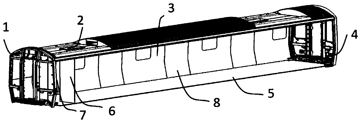
[0017] refer to figure 1 , The rail vehicle body usually includes a front end 1 , a roof 2 , a side wall 3 , a rear end 4 , and an underframe 5 . The five-part structure forms a complete enclosed space for carrying passengers and other equipment of the vehicle. There is often a driver's cab partition 6 inside this space. The space inside the vehicle is divided into two parts by the partition wall 6 of the driver's compartment: the driver's compartment 7 and the passenger compartment 8 . Most of the U.S. subway rail vehicles are required to be able to ensure the safety of the driver when a 6-car formation collides at 24 kilometers per hour, and to ensure the safety of the passenger compartment when a 6-car formation collides at a speed of 40 kilometers per hour. That is, when the impact speed is less than 24 kilometers per hour, the driver's cab 7 needs to have enough living space. When the impact speed is less than 40 kilometers per hour, the cabin 8 needs to have enough li...


PUM


Abstract

The invention discloses a railway vehicle collision pillar. The collision pillar comprises an upper segment, a middle segment and a lower segment welded in order, three sections are hollow steel; a non-mounting surface of the upper section is a slope, the middle section is formed by butt-welding two U-shaped plates, and the bottom side of one U-shaped plate is an obtuse angle bending plate; the lower section is formed by splicing four peripheral steel plates; one bending plate is engaged with the middle section U-shaped bending plate; stiffener boards are arranged on inner sides of the upper section and the middle section, a layer of vertical stiffener board is at least arranged at the internal of the lower section, a long round hole is formed in a connecting region of the upper part of the lower section and the middle section, the lower section is inserted into the middle section to fixedly weld with the middle section at the long round hole. The rigidity requirement, the space requirement, the mass requirement, the function requirement, and the manufacturability requirement of the vehicle entire design can be met, the reinforcement of the collision pillar is realized through theminimum mass introduction, the security is realized, and the damage on other components by the collision is reduced.

Description

technical field [0001] The invention belongs to the field of railway transportation, and in particular relates to a head collision column structure for subway vehicles. Background technique [0002] With the development of society, subway vehicles are becoming more and more popular in densely populated cities, and everyone has higher and higher requirements for the safety of subway vehicles. The European standard EN 15227 stipulates that the front end of the rail vehicle body should have structural passive safety, that is, it is necessary to set an energy absorption area within a certain range of the front end of the car body. North American Railroad Association standard AAR S-580 stipulates that two collision posts and two corner posts must be arranged at the front of the driver's cab, and both the collision posts and the corner posts must have sufficient strength to resist collision damage. The front end design of the existing rail vehicle generally combines the above two...

Claims


Application Information

Patent Timeline
Patent Type & Authority Applications(China)
IPC IPC(8): B61D15/06B61F19/04
Inventor 刘洪涛洪海峰董华新骆起刘立玺
Owner CRRC CHANGCHUN RAILWAY VEHICLES CO LTD
Features
  • Generate Ideas
  • Intellectual Property
  • Life Sciences
  • Materials
  • Tech Scout
  • Unparalleled Data Quality
  • Higher Quality Content
  • 60% Fewer Hallucinations
Learn More