
Adjacent space propeller with tip actively blowing air

A near-space, propeller technology, applied in propellers, transportation and packaging, aircraft parts, etc., can solve the problems of the complete consistency of centrifugal force, the influence of propeller structural strength, and the complexity of the synergistic jet mechanism. , centrifugal force and the effect of small deviation of centrifugal force

Active Publication Date: 2021-07-13
BEIHANG UNIV
View PDF5 Cites 0 Cited by
  • Summary
  • Abstract
  • Description
  • Claims
  • Application Information

AI Technical Summary

Problems solved by technology

Its disadvantages and deficiencies are: (1) The cooperative jet mechanism is complicated, and the installation space required to install multiple cooperative jet mechanisms is large, which has a great impact on the structural strength of the propeller
(2) When the propeller rotates at high speed, the multiple devices arranged inside the blade will be subjected to a large centrifugal force, and it is difficult for the centrifugal force received by different blades to be exactly the same
This will not only increase the tensile stress on the blade, but also cause the root of the blade and the propeller shaft to be subjected to alternating tensile stress during operation, which is prone to fatigue damage
(3) Arranging multiple sets of complex cooperative jet devices, paying a large energy price but only obtaining a 5% gain in aerodynamic efficiency

Method used


Image

  • Adjacent space propeller with tip actively blowing air
  • Adjacent space propeller with tip actively blowing air
  • Adjacent space propeller with tip actively blowing air

Examples


Embodiment Construction

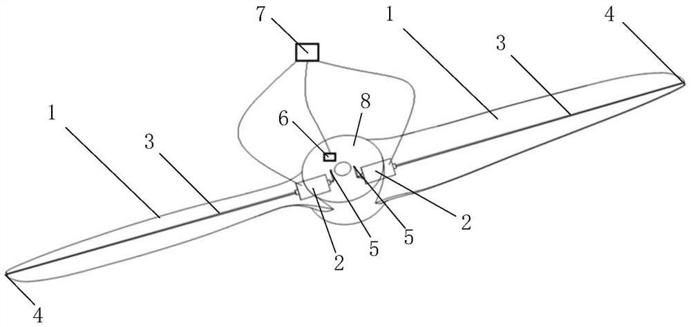
[0024] Attached below Figure 1-6 , the present invention will be further described from the air blowing system layout, air blowing control and practical application effect.

[0025] The present invention provides a kind of adjacent space propeller that propeller tip actively blows air, such as figure 1 , figure 2 and image 3 As shown, the propeller includes a blade 1 and a hub 8. Taking a propeller with two blades 1 as an example, the present invention is provided with an air pump 2, an airflow conduit 3, an air blowing port 4, and an air suction port 5 on the propeller. , the acceleration sensor 6 and the control circuit 7, the control circuit 7 controls the work of the air pump 2, and the gas in the suction port 5 is passed through the airflow conduit 3, and is ejected at the blowing port 4 to form the active blowing of the tip of the paddle. Both the acceleration sensor 6 and the control circuit 7 are located inside the hub 8 . There are two suction ports 5, two air ...


PUM


Abstract

The invention discloses a near-space propeller with a propeller tip actively blowing air, and belongs to the field of propeller design. The propeller includes an air pump, an airflow duct, an air blowing port, an air intake port, an acceleration sensor and a control circuit. The air pump is located in the propeller hubs on both sides of the propeller shaft, the acceleration sensor and the control circuit are located inside the propeller hub, and the airflow duct is located in the propeller. Inside the blades on both sides of the propeller hub, air blowing ports are respectively provided on the lower surfaces of the propeller tips at both ends of the propeller, and air inlets are respectively provided on the windward surfaces of the propeller hub on both sides of the propeller shaft. The air outlet end of the air pump is communicated with the air inlet end of the air flow conduit, the air outlet end of the air flow conduit is communicated with the air blowing port, and the control circuit is electrically connected with the two air pumps and the acceleration sensor respectively. The propeller provided by the present invention effectively weakens the strength of the propeller tip vortex by setting the blowing power coefficient of the blowing port when blowing air, so as to achieve the purpose of increasing the pulling force and improving the efficiency.

Description

technical field [0001] The invention belongs to the field of propeller design, and in particular relates to a propeller in an adjacent space whose tip actively blows air, which can improve the aerodynamic characteristics of the propeller and improve the aerodynamic efficiency of the propeller by weakening the tip vortex. Background technique [0002] Propellers of near-space vehicles work at altitudes above 20km, and the density of the atmosphere is less than one-tenth of that at sea level. The size of propellers is generally large, and the working Reynolds number is in the range of 200,000 to 600,000. Due to the characteristics of the working conditions of the propellers of near-space vehicles, it is difficult to improve their aerodynamic performance through conventional propeller design methods, and it is difficult to meet the performance requirements of near-space vehicles for propellers. By controlling the propeller tip flow, the aerodynamic performance can be significan...

Claims


Application Information

Patent Timeline
Patent Type & Authority Patents(China)
IPC IPC(8): B64C11/18B64C11/02
Inventor 马东立姚远杨穆清张良陈刚
Owner BEIHANG UNIV
Learn More