
A radar beam decoupling method for a moving platform

A motion platform and radar beam technology, applied in the field of radar beam decoupling, can solve problems such as gimbal lock, increase computational complexity, and loss of decoupling ability, so as to reduce complexity, realize simple calculation, and reduce calculation amount Effect

Active Publication Date: 2021-02-19
成都汇蓉国科微系统技术有限公司
View PDF9 Cites 0 Cited by
  • Summary
  • Abstract
  • Description
  • Claims
  • Application Information

AI Technical Summary

Problems solved by technology

However, when using the Euler rotation matrix for beam decoupling, if some coordinate axes coincide, there will be a gimbal lock problem, thus losing the decoupling ability in one direction
At the same time, the Euler rotation matrix in this method requires multiple trigonometric operations, and the amount of calculation is large
[0004] Chinese patent document CN102981151A aims at the problem that after the phased array is directly connected to the moving carrier, the disturbance of the carrier will directly act on the array antenna, causing the antenna beam to change in space, and provides a phased array radar electronically controlled beam stabilization method, this method uses the principle of beam spatial pointing invariance, at the moment when the rising edge of the beam stable frame signal arrives, the relative attitude at the current moment is solved, and the antenna beam azimuth and pitch required to make the beam still point to the target tracking vector at the previous moment are obtained angle, and then derive the compensation angle required to counteract the disturbance
However, the method disclosed in this patent requires iterative calculation every time the quaternion vector of the next moment is calculated, which results in a significant increase in the complexity of the calculation

Method used


Image

  • A radar beam decoupling method for a moving platform
  • A radar beam decoupling method for a moving platform
  • A radar beam decoupling method for a moving platform

Examples


Embodiment Construction

[0033] The technical solution of the present invention will be described in detail below in conjunction with the accompanying drawings.

[0034] The coordinate system mentioned in the present invention is defined as follows:

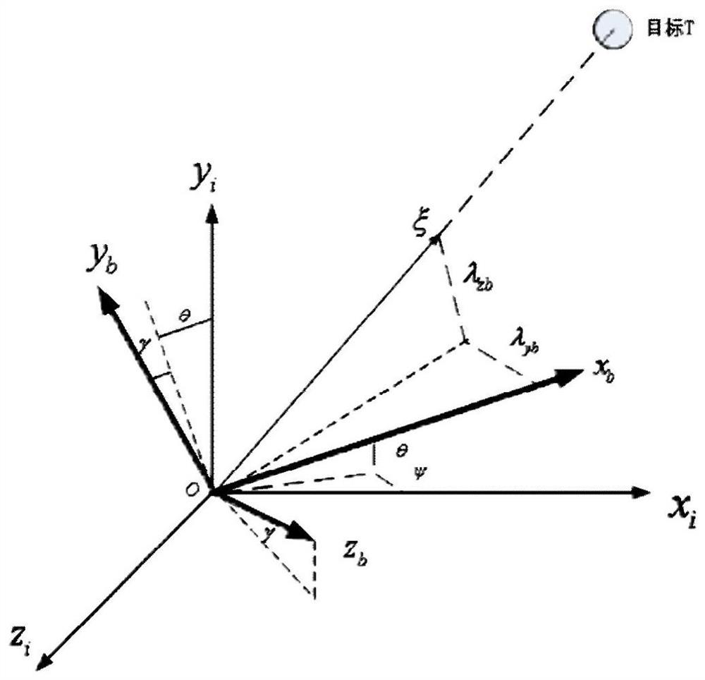
[0035] Such as figure 1 As shown, the inertial coordinate system in the present invention takes the radar center of mass O as the origin, and x i pointing due north, y i Pointing to the sky, z is determined according to the right-hand rule i . The carrier coordinate system is a coordinate system obtained by rotating the inertial coordinate system according to the three attitude angles of the radar's pitch, yaw and roll.

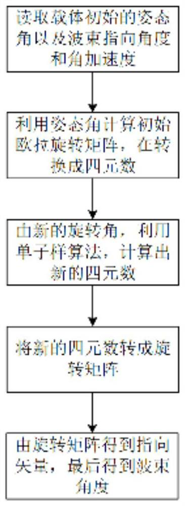
[0036] Such as figure 2 As shown, the moving platform radar beam decoupling method disclosed in the present invention includes the following steps:

[0037] Step 1: Obtain the three attitude angles of the motion platform in the inertial coordinates under the initial conditions: pitch angle θ, yaw angle ψ, roll angle γ, the azimut...


PUM


Abstract

The invention discloses a radar beam decoupling method of a moving platform, which comprises the following steps: Step 1. Acquiring three attitude angles of the moving platform under initial conditions under inertial coordinates: pitch angle θ, yaw angle ψ, and roll angle γ; Step 2. Calculate the Euler rotation matrix C of the initial motion platform in the inertial coordinate system, and convert the Euler rotation matrix C into a quaternion; Step 3. Solve the new quaternion formed by the rotation of the carrier at the next moment Vector Q 1 ; Step 4, from the updated quaternion vector Q 1 Compute the new Euler rotation matrix C 1 ; Step 5, using the new Euler rotation matrix C 1 Calculate the updated beam azimuth α 1 , pitch angle β 1 . Due to the adoption of the above solution, compared with the prior art, the present invention simplifies the calculation steps, reduces the calculation amount, and can realize fast decoupling.

Description

technical field [0001] The invention relates to radar beam decoupling technology, in particular to a radar beam decoupling method under a moving platform. Background technique [0002] Radar systems (such as pulse Doppler radar for detecting low-slow and small targets and synthetic aperture radar for imaging) are not affected by weather conditions and can detect targets all-weather and all-weather, and are widely used in military and civilian fields. In particular, radar application platforms, such as airborne, spaceborne, and vehicle-mounted platforms, are becoming more and more abundant. Under these moving platforms, due to the turbulence and vibration of the carrier, the beam pointing of the radar will change, which will cause the performance index of the radar to decline and affect the normal use of the radar. [0003] The purpose of radar beam decoupling is to ensure that the beam pointing of the radar under the moving platform does not change with the bumps and jitter...

Claims


Application Information

Patent Timeline
Patent Type & Authority Patents(China)
IPC IPC(8): G01S7/36G01S7/40G01S13/88
Inventor 邹江波鲁瑞莲何东
Owner 成都汇蓉国科微系统技术有限公司
Learn More