
Synchronous rectification control circuit and method

A synchronous rectification and control circuit technology, applied in the control/regulation system, electrical components, regulating electrical variables, etc., can solve the problems of inconsistent MOS tube conduction, excessive primary current, damage to the switch tube, etc., and achieve reliable detection. , Improve the conversion efficiency, the effect of voltage mutation is obvious

Pending Publication Date: 2019-05-17
SHENZHEN XILIN ELECTRICAL TECH
View PDF0 Cites 4 Cited by
  • Summary
  • Abstract
  • Description
  • Claims
  • Application Information

AI Technical Summary

Problems solved by technology

[0010] The purpose of the present invention is to solve the problem that in the existing synchronous rectification mode, when the resonant frequency in the LLC resonant circuit is higher than the switching frequency, the secondary side current is ahead of the primary side drive to zero, if the secondary side drive is still synchronous with the primary side. If it is not connected in time and disconnected in advance, there will be a risk of excessive primary current or even damage to the switch tube. The Yada ORing field effect tube control method has very high requirements on the symmetrical modules and components inside the circuit, which is caused by parasitic inductance and lead inductance. The driving voltage is high and low, which causes the conduction degree of the MOS transistor to be inconsistent, and the efficiency is greatly affected.

Method used


Image

  • Synchronous rectification control circuit and method
  • Synchronous rectification control circuit and method
  • Synchronous rectification control circuit and method

Examples


Embodiment Construction

[0056] The following will clearly and completely describe the technical solutions in the embodiments of the present invention with reference to the drawings in the embodiments of the present invention. Apparently, the described embodiments are only some of the embodiments of the present invention, but not all of them. Based on the embodiments of the present invention, all other embodiments obtained by persons of ordinary skill in the art without creative efforts fall within the protection scope of the present invention.

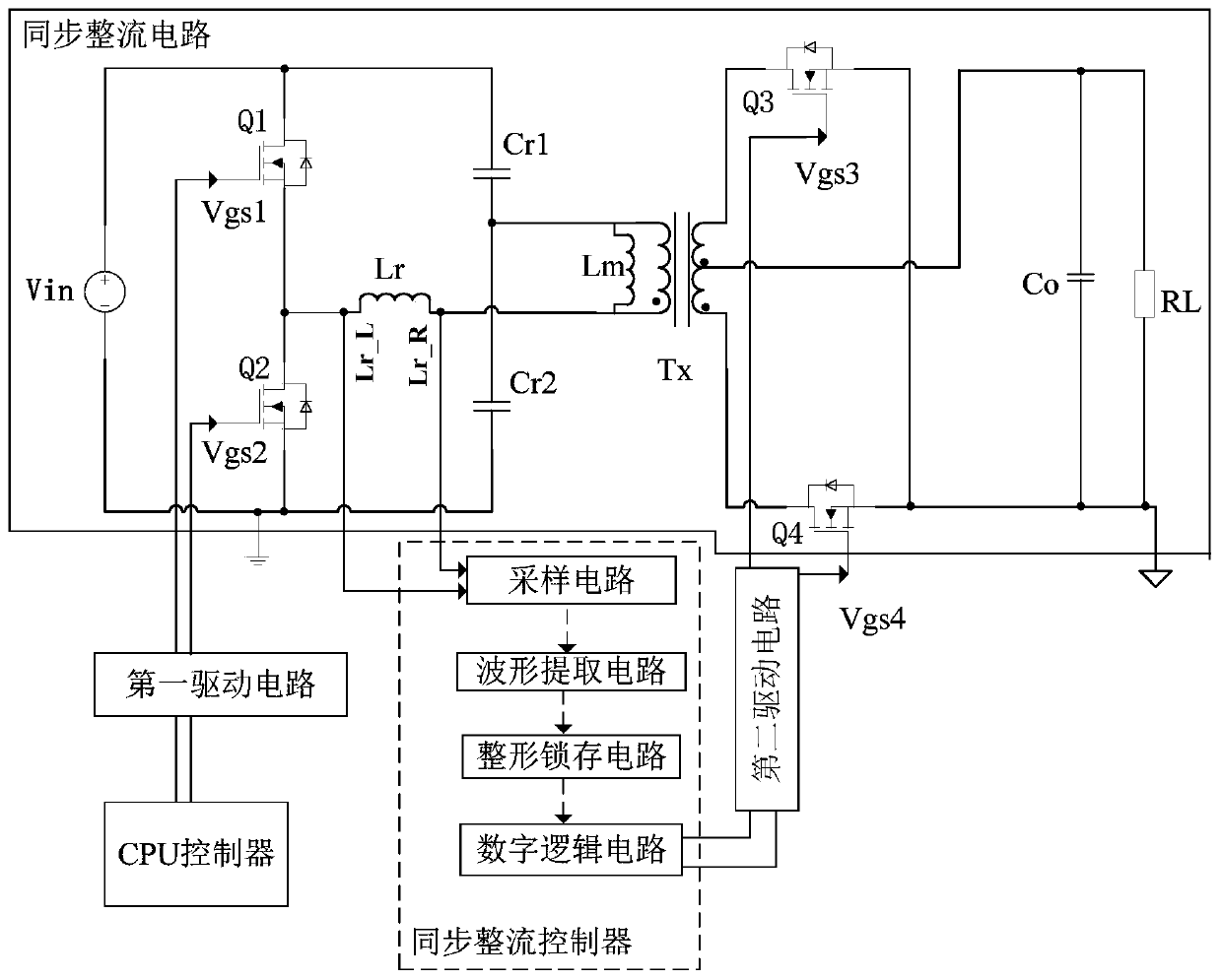
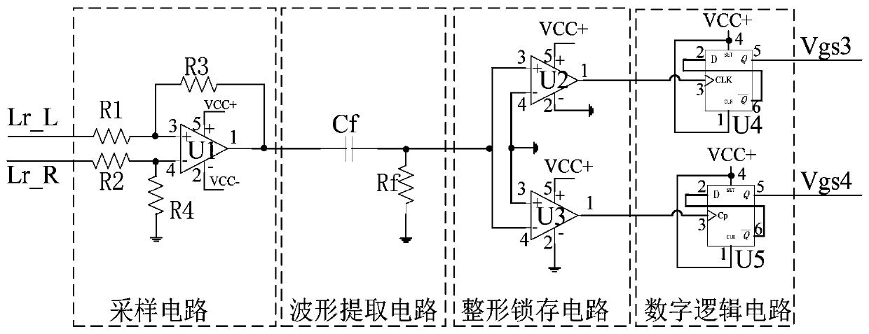
[0057] like figure 2 , 3 As shown, a synchronous rectification control circuit includes a synchronous rectification circuit, the output of the first drive circuit is connected to the primary side of the synchronous rectification circuit, the output of the second drive circuit is connected to the secondary side of the synchronous rectification circuit, and the CPU controller is connected to the first driver Circuit input connection. It also includes a sync...


PUM


Abstract

The present invention provides a synchronous rectification control circuit. The synchronous rectification control circuit comprises a synchronous rectification circuit, a first drive circuit having anoutput connected with a primary side of the synchronous rectification circuit, a second drive circuit having an output connected with a secondary side of the synchronous rectification circuit, and aCPU controller connected with the input of the first drive circuit. The synchronous rectification control circuit further comprises a synchronous rectification controller having one end connected withthe primary side of the synchronous rectification circuit and having the other end connected with the input of the second drive circuit. The synchronous rectification controller comprises a samplingcircuit, a waveform extraction circuit, a shaping latch circuit and a digital logic circuit. According to the scheme, the instantaneous abrupt of a resonance voltage Lr is detected to determine starting and stopping of a secondary side current to control conduction and cut-off of a synchronous rectification MOS tube. The synchronous rectification control circuit does not need real-time tracking ofprimary side drive, can be applied in an all switching frequency range without influence of the switching frequency, and can perform real-time tracking of the synchronous control of the output current so as to improve the conversion efficiency.

Description

technical field [0001] The invention relates to the technical field of rectification and rectification, in particular to a synchronous rectification control circuit and method. Background technique [0002] With the improvement of power supply efficiency requirements, synchronous rectification technology has attracted more and more people's attention, especially in DC / DC low-voltage and high-current applications. It has increasingly become a trend to use MOSFET (Metal-Oxide-Semiconductor Field-Effect Transistor abbreviation, Chinese for Metal-Oxide-Semiconductor Field-Effect Transistor) instead of simple diode rectification to reduce losses and improve efficiency. [0003] The existing synchronous rectification technology has the following defects: [0004] (1) One of the existing synchronous rectification methods is to use the primary side to follow the secondary side control technology, that is, the secondary side drive and the primary side drive are completely synchroniz...

Claims


Application Information

Patent Timeline
IPC IPC(8): H02M3/335
CPCY02B70/10
Inventor 韩云龙
Owner SHENZHEN XILIN ELECTRICAL TECH
Learn More