Non-isocentric rotary intensity-modulated radiotherapy device

An intensity-modulated radiation therapy and isocentric technology, which is applied in X-ray/γ-ray/particle irradiation therapy, etc., can solve the problem of patient collision between the rack and the treatment bed, the failure of the tumor target area to be irradiated, and the inability to obtain sufficient doses, etc. problems, to achieve the effect of improving the central dose rate and clinical treatment efficiency, improving clinical treatment efficiency, and realizing miniaturization

Pending Publication Date: 2019-05-21
上海伽玛星科技发展有限公司
View PDF6 Cites 0 Cited by
  • Summary
  • Abstract
  • Description
  • Claims
  • Application Information

AI Technical Summary

Problems solved by technology

[0004] In clinical applications, the currently used isocentric rotating intensity-modulated irradiation has the following disadvantages: 1. The beam of the handpiece is always aligned with the center of rotation of the equipment, that is, the irradiation center and the center of rotation always coincide, and this point is usually called the isocenter
When the position of the tumor target area deviates from the isocenter position of the device, the tumor target area cannot be irradiated, and a sufficient dose cannot be obtained
2. Since the location of the tumor in different patients is different, in most cases the tumor is not located in the center of the patient's body, but may be on the side of the body
After the rotation radius of the equipment is increased, the treatment accuracy will be reduced
3. Since the dose rate of radiation is inversely proportional to the square of the irradiation distance, the dose rate of the device will decrease rapidly after the rotation radius of the device increases, which leads to a decrease in the efficiency of clinical treatment
4. Since the patient is often not in the center of the equipment, but shifted to one side of the equipment, there is a possibility of collision between the gantry and the treatment bed (or patient) when the gantry rotates or moves the treatment bed for non-coplanar irradiation treatment. risk

Method used


Image

  • Non-isocentric rotary intensity-modulated radiotherapy device

Examples


Embodiment Construction

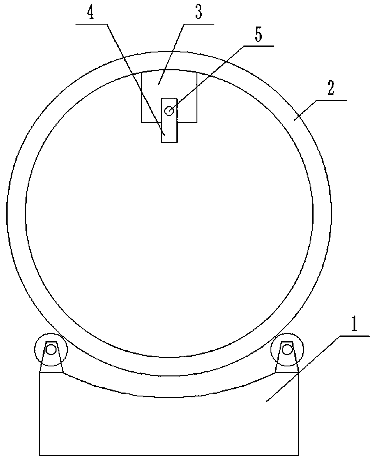
[0013] like figure 1 As shown, a non-isocentric rotating intensity modulated radiation therapy device of the present invention includes a base 1, a roller 2, a treatment head frame 3 and a treatment head 4, the roller 2 is movably arranged in the base 1, and the roller 2 Can do circular motion in the base 1 along with its central axis, the treatment head frame 3 is fixedly arranged on the inner wall of the drum 2, the treatment head 4 is movably arranged on the treatment head frame 3 through the rotating shaft 5, and the The treatment head 4 can be rotated with the rotating shaft 5, so that the beam emitted by the treatment head 4 can swing radially instead of always hitting the isocenter.

[0014] The rotating shaft 5 is driven by a driving mechanism arranged in the treatment head frame 3 .

[0015] The driving mechanism is a stepping motor, and the stepping motor is electrically connected with the control module, and the precise movement of the stepping motor is controlled ...


PUM


Abstract

The invention overcomes defects in the prior art, provides a non-isocentric rotary intensity-modulated radiotherapy device, the volume of equipment is reduced, the central dose rate and the clinical treatment efficiency are improved, and the risk of collision between a frame and a treatment bed (or a patient) is eliminated; in order to solve the technical problems, the technical scheme adopted isas follows: the non-isocentric rotary intensity-modulated radiotherapy device comprises a base, a roller, a treatment head frame and a treatment head, wherein the roller is movably arranged on the base and can make circular motion on the base in the own central axis; the treatment head frame is fixedly arranged on the inner wall of the roller, the treatment head is movably arranged on the treatment head frame through a rotating shaft, and the treatment head can rotate with the rotation shaft, so that the beam emitted by the treatment head does not always shoot to an isocenter; the non-isocentric rotary intensity-modulated radiotherapy device can be widely applied to the technical field of radiation therapy.

Description

technical field [0001] The invention relates to a non-isocentric rotating intensity modulated radiation therapy device, which belongs to the technical field of radiation therapy. Background technique [0002] Radiation therapy (referred to as radiotherapy) is an important tumor treatment method. This method uses ionizing radiation (Ionizing Radiation) to kill tumor cells. Precision radiotherapy is an important development direction in the field of radiotherapy. According to clinical needs, precision radiotherapy has two main optimization goals in the design of radiotherapy plans: 1) accurately project radiation on the tumor target area, and 2) minimize radiation exposure to organs at risk and normal organs. In order to meet these two optimization goals at the same time, improve the treatment efficiency, expand the range of ray incident angles, and better reduce the dose of surrounding normal organs and crisis organs, rotational intensity-modulated irradiation technology is...

Claims


Application Information

Patent Timeline
Patent Type & Authority Applications(China)
IPC IPC(8): A61N5/10
Inventor 张文山
Owner 上海伽玛星科技发展有限公司
Why Eureka
Try Eureka