A Plasma Device Driving Magnetic Reconnection

A technology of plasma and plasma source, applied in the application field of plasma, can solve the problem that the simulation device cannot actually study the three-dimensional magnetic reconnection process

Active Publication Date: 2021-09-03
HARBIN INST OF TECH
View PDF5 Cites 0 Cited by
  • Summary
  • Abstract
  • Description
  • Claims
  • Application Information

AI Technical Summary

Problems solved by technology

[0005] The present invention aims to solve the problem that the existing space plasma ground simulation device cannot truly study the three-dimensional magnetic reconnection process in space. The present invention provides a plasma device for driving magnetic reconnection

Method used


Image

  • A Plasma Device Driving Magnetic Reconnection
  • A Plasma Device Driving Magnetic Reconnection
  • A Plasma Device Driving Magnetic Reconnection

Examples


Embodiment 1

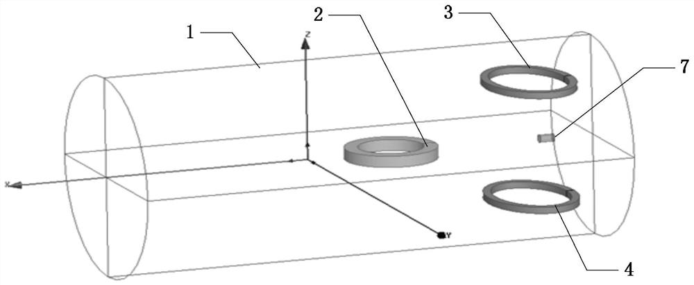
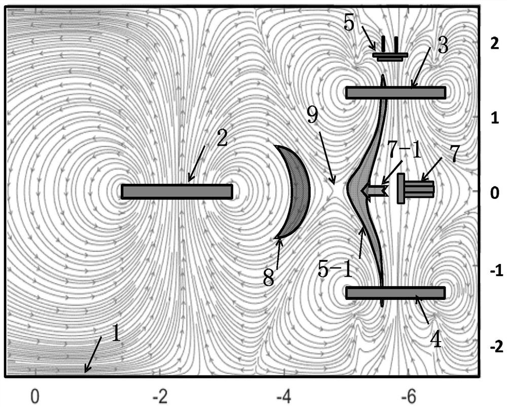
[0049] see figure 2 Describe this embodiment, a plasma device for driving magnetic reconnection described in this embodiment includes an electron cyclotron resonance plasma source, a vacuum chamber 1, and a dipole magnetic field coil 2 arranged in the vacuum chamber 1, Upper magnetic mirror field coil 3, lower magnetic mirror field coil 4, upper LaB 6 Plasma source 5 and plasma gun 7;

[0050] Working gas is contained in the vacuum chamber 1;

[0051] After the dipole magnetic field coil 2 is energized, it generates a magnetic field that simulates the configuration of the earth's magnetic field;

[0052] The electron cyclotron resonance plasma source is arranged outside the vacuum chamber 1, and the electron cyclotron resonance plasma source generates the magnetopause earth-side plasma 8 under the magnetic field of the configuration of the earth's magnetic field;

[0053] The upper magnetic mirror field coil 3 and the lower magnetic mirror field coil 4 are relatively arran...

Embodiment 2

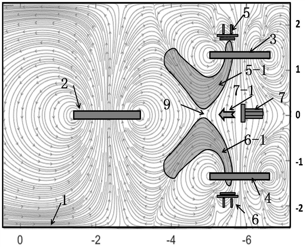
[0073] see figure 1 with image 3 Describe this embodiment, a kind of plasma device that drives magnetic reconnection described in this embodiment, comprises vacuum chamber 1, and the dipole magnetic field coil 2 that is arranged in vacuum chamber 1, upper magnetic mirror field coil 3, Lower magnetic mirror field coil 4, upper LaB 6 Plasma source 5, lower LaB 6 Plasma source 6 and plasma gun 7;

[0074] Working gas is contained in the vacuum chamber 1;

[0075] After the dipole magnetic field coil 2 is energized, it generates a magnetic field that simulates the configuration of the earth's magnetic field;

[0076] The upper magnetic mirror field coil 3 and the lower magnetic mirror field coil 4 are relatively arranged in the vertical direction, and the magnetic field generated by the two is used to simulate the configuration of the Earth's magnetotail, the magnetic field of the Earth's magnetotail configuration and the magnetic field of the Earth's magnetic field configura...


PUM


Abstract

A plasma device for driving magnetic reconnection belongs to the application technical field of low temperature plasma. It solves the problem that the existing space plasma ground simulation device cannot truly study the three-dimensional magnetic reconnection process in space. The present invention can realize magnetopause magnetic reconnection and magnetotail magnetic reconnection; when magnetopause magnetic reconnection is realized, the configuration of the earth's magnetic field is simulated through the dipole magnetic field coil, the configuration of the interplanetary magnetic field is simulated through the magnetic mirror field coil, and the configuration of the interplanetary magnetic field is simulated through the The plasma beam jetted by the plasma gun reconnects the magnetosphere side plasma formed on the Earth's magnetic field configuration and the magnetopause magnetosheath side plasma formed on the interstellar magnetic field configuration at the magnetic zero point; When connected, the dipole magnetic field coil is energized to simulate the configuration of the earth's magnetic field, and the magnetic mirror field coils are used to simulate the configuration of the magnetic field of the earth's magnetotail. The magnetic zero position achieves reconnection. The invention is mainly used to drive the magnetic reconnection process to occur.

Description

technical field [0001] The invention belongs to the application technical field of low-temperature plasma, and in particular relates to a space plasma device which can be used to drive the magnetic reconnection process to occur. Background technique [0002] The most direct way to study the space plasma environment and its interaction with spacecraft is to use space detection. Through a large number of satellite observations, people have made great achievements in the study of the space plasma environment and its physical processes. However, space satellite detection is difficult to obtain global observation data at the same time. Therefore, while extensively carrying out space exploration and on-orbit experiments, establishing ground simulation devices and conducting ground simulation research on space science experiments have important scientific value and urgent practical significance for the progress of scientific frontiers and major national needs. [0003] The ground...

Claims


Application Information

Patent Timeline
Patent Type & Authority Patents(China)
IPC IPC(8): B64G7/00H05H1/16
Inventor 肖青梅鄂鹏王晓钢
Owner HARBIN INST OF TECH
Why Eureka
Try Eureka