Spun yarn winding device for textile machine

A winding device and textile machinery technology, applied in the textile field, can solve the problems of affecting the quality of spinning yarn, poor spinning uniformity, carrying large dust, etc., and achieve the effect of reducing operation difficulty, smooth winding of thin wire, and beautiful winding finished product

Inactive Publication Date: 2019-05-21
海安县新华伦纺织有限公司
View PDF0 Cites 5 Cited by
  • Summary
  • Abstract
  • Description
  • Claims
  • Application Information

AI Technical Summary

Problems solved by technology

[0004] The purpose of this application is to provide a spinning thread winding device for textile machinery, to solve the problem that the traditional spinning thread winding device proposed in the above background technology uses manual coil winding, which increases fatigue, and the winding efficiency is too low, and it is not easy to operate in the factory. Winding and spinning will easily cause a large amount of dust to be carried in the coil, which will affect the quality of the spinning after long-term storage, and the uniformity of the spinning wound by the traditional winding device is poor, and the spinning is prone to problems such as knotting

Method used


Image

  • Spun yarn winding device for textile machine
  • Spun yarn winding device for textile machine
  • Spun yarn winding device for textile machine

Examples


Embodiment Construction

[0021] The following will clearly and completely describe the technical solutions in the embodiments of the application with reference to the drawings in the embodiments of the application. Apparently, the described embodiments are only some of the embodiments of the application, not all of them. Based on the embodiments in this application, all other embodiments obtained by persons of ordinary skill in the art without making creative efforts belong to the scope of protection of this application.

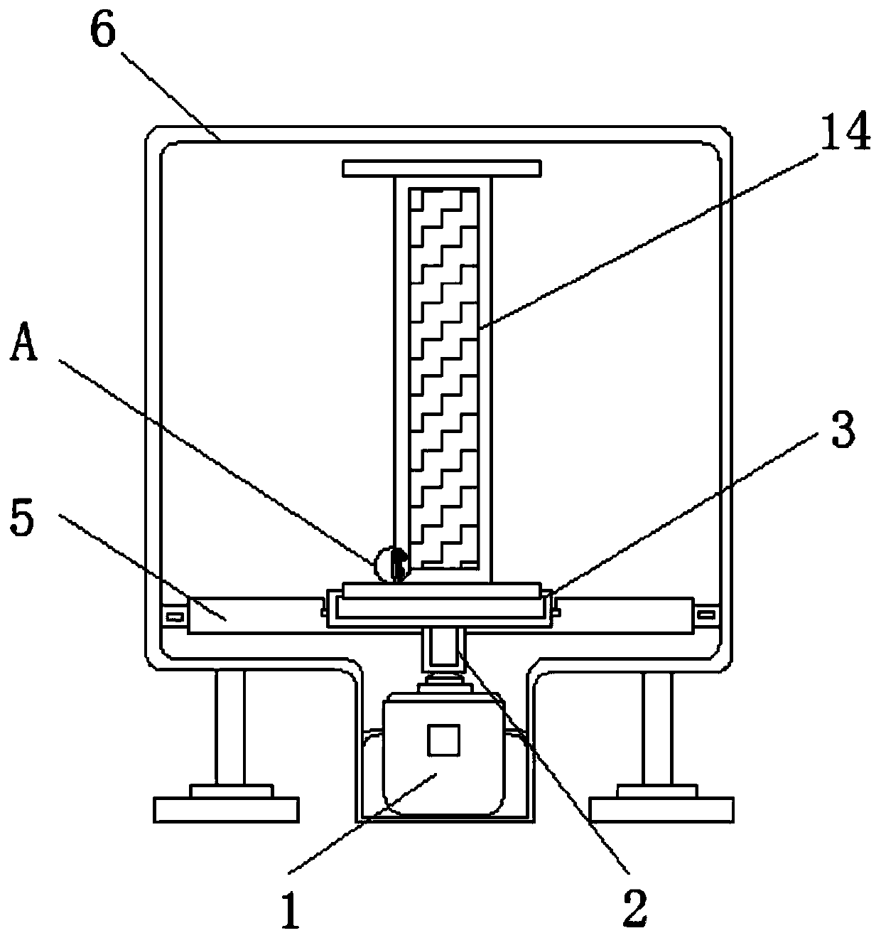
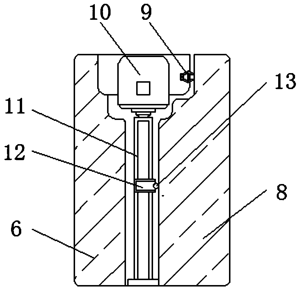
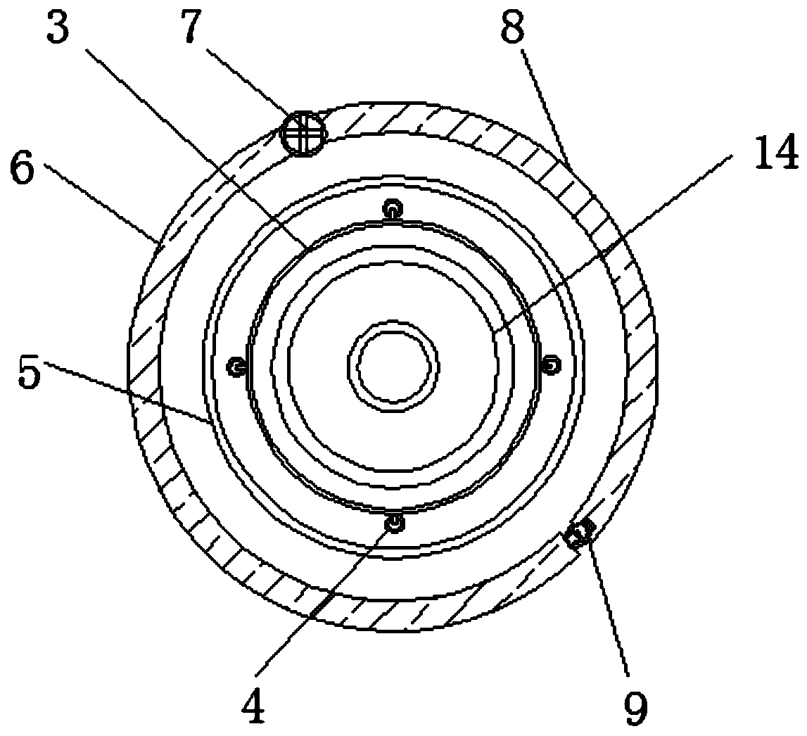
[0022] see Figure 1-4 , including a rotating motor 1 and a screw mandrel 11, a rotating roller 2 is connected to the top of the rotating motor 1, and a rotating table 3 is fixedly installed on the upper port of the rotating roller 2, and a runner 4 is fixedly installed on the left and right sides of the rotating table 3, And the outer side of runner 4 is movably connected with base 5, and the outer side of base 5 is fixedly installed with device left shell 6, and the side surface o...


PUM


Abstract

The invention discloses a spun yarn winding device for a textile machine. The spun yarn winding device comprises a rotary motor and a lead screw. The upper portion of the rotary motor is connected with a rotary roll, and a rotary table is fixedly mounted on an upper end opening of the rotary roll. Rotary wheels are fixedly mounted on the left side and the right side of the rotary table, and the outer sides of the rotary wheels are movably connected with a base. A device left shell is fixedly mounted on the outer side of the base, and the side surface of the device left shell is movably connected with a rotary shaft. A device right shell is fixedly mounted on the right side of the rotary shaft, and a buckle is fixedly mounted on the side face of the device right shell. A servo motor is arranged on the left side of the buckle, and the lead screw is mounted below the servo motor. The outer surface of the lead screw is movably connected with a workbench, and a yarn passing hole is formed in the workbench. A fixed pile is fixedly mounted below a spring. The spun yarn winding device for the textile machine mainly has the beneficial effects that spun yarn is vertically tiled outside a coiling block, so that the spun yarn is wound more smoothly, and then the phenomenon of spun yarn knotting is avoided.

Description

technical field [0001] The present application relates to the technical field of textiles, in particular to a spinning thread winding device for textile machinery. Background technique [0002] Spinning thread is the main production item in the traditional farming and weaving society in China. With the rapid development of Chinese society, people's lifestyles have undergone tremendous changes. Traditional handicrafts have gradually been replaced by modern machinery. Nowadays, there are more and more types of textile machinery. Compared with the traditional handicraft, the efficiency is greatly improved. [0003] The traditional spun yarn winding device uses manual winding of the coil, which increases fatigue, and the winding efficiency is too low, and winding the spun yarn in the factory will easily cause a large amount of dust to be carried in the coil, which will affect the quality of the spun yarn after long-term storage, and the traditional The uniformity of the spinnin...

Claims


Application Information

Patent Timeline
Patent Type & Authority Applications(China)
IPC IPC(8): B65H54/74B65H54/72B65H54/28B65H75/28
Inventor 韩金芳
Owner 海安县新华伦纺织有限公司
Why Eureka
Try Eureka