
Caterpillar transmission chain link full-automatic tempering processing device and operation method thereof

A technology of crawler transmission and processing equipment, applied in heat treatment equipment, manufacturing tools, furnaces, etc., can solve the problems of poor tempering treatment quality of chain rail links, uneven heat distribution, and the need to distinguish left and right chain rail links, etc., to improve Tempering quality, improved heat uniformity, effect of improved uniformity

Pending Publication Date: 2019-05-21
双威大昌锻造(安徽)有限公司
View PDF7 Cites 0 Cited by
  • Summary
  • Abstract
  • Description
  • Claims
  • Application Information

AI Technical Summary

Problems solved by technology

[0003] The purpose of the present invention is to overcome the problems of uneven heat distribution in the tempering furnace existing in the tempering treatment device for chain rail joints, the need to distinguish the left and right of the chain rail joints after tempering, and the poor quality of the tempering treatment of the chain rail joints, and provide A fully automatic tempering processing equipment for crawler belt drive chain rail joints with reasonable structural design, good heat distribution uniformity in the tempering furnace, no left and right distinction between tempered chain rail joints, and high chain rail joint tempering quality. operation method

Method used


Image

  • Caterpillar transmission chain link full-automatic tempering processing device and operation method thereof
  • Caterpillar transmission chain link full-automatic tempering processing device and operation method thereof
  • Caterpillar transmission chain link full-automatic tempering processing device and operation method thereof

Examples


Embodiment 1

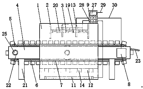
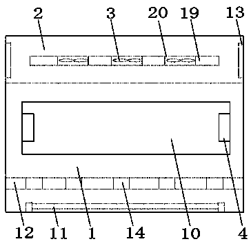
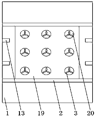
[0034] as attached Figure 1-7 As shown in the figure, a fully automatic tempering processing equipment for track transmission chain rail joints, including a tempering furnace 1, a partition 2, a fan 3, a beam 4, a transmission roller 5, a transmission belt 6, a load plate 7, a motor 8 and a controller 9 It is characterized in that: the opposite sides of the tempering furnace 1 are provided with inlets and outlets 10 through the tempering furnace 1, a heating pipe 11 with a horizontal structure is arranged at the inner bottom of the tempering furnace 1, and on the inner wall 18 at the top of the tempering furnace 1 The second heating pipe 13 of the vertical structure is provided, and the second heating pipe 13 is arranged on the inner wall 18 of the tempering furnace 1 between the partition plate 2 and the partition plate 2, and the flow from the inlet and outlet 10 on the tempering furnace 1 can be reduced by the partition plate 2 Heat, so that the heat in the tempering furna...

Embodiment 2

[0048] as attached Figure 8-11 As shown in the figure, a fully automatic tempering processing equipment for track transmission chain rail joints, including a tempering furnace 1, a partition 2, a fan 3, a beam 4, a transmission roller 5, a transmission belt 6, a load plate 7, a motor 8 and a controller 9 It is characterized in that: the opposite sides of the tempering furnace 1 are provided with inlets and outlets 10 through the tempering furnace 1, a heating pipe 11 with a horizontal structure is arranged at the inner bottom of the tempering furnace 1, and on the inner wall 18 at the top of the tempering furnace 1 The second heating pipe 13 of the vertical structure is provided, and the second heating pipe 13 is arranged on the inner wall 18 of the tempering furnace 1 between the partition plate 2 and the partition plate 2, and the flow from the inlet and outlet 10 on the tempering furnace 1 can be reduced by the partition plate 2 Heat, so that the heat in the tempering furn...


PUM


Abstract

The invention discloses a caterpillar transmission chain link full-automatic tempering processing device. The caterpillar transmission chain link full-automatic tempering processing device comprises atempering furnace, a separation plate, a fan, beams, a conveying roller, a conveyer belt, bearing plates, a motor and a controller. The caterpillar transmission chain link full-automatic tempering processing device is characterized in that inlet and outlets penetrating through the tempering furnace are formed in both the two opposite sides of the tempering furnace, the separation plate is perpendicularly arranged on the top of the interior of the tempering furnace, the fan is installed in a fan installation hole, the beams transversely penetrate through the inlet and outlets, the two ends ofeach beam are arranged on a support, and the two ends of the conveying roller are arranged on connecting shafts. According to the caterpillar transmission chain link full-automatic tempering processing device, a discharging plate is arranged between every two adjacent beams, a limiting groove is formed in each discharging plate, chain links subjected to tempering processing move along with rotation of the conveyer belt, and the chain links are transferred out through the inlet and outlets in the tempering furnace and slide into corresponding collection boxes through the discharging plates; andbecause of the limiting grooves, it is avoided that limiting plates on the bearing plates make contact with the discharging plates, and the conveyer belt can rotate normally while the chain links aredischarged.

Description

technical field [0001] The invention relates to the technical field of chain rail joint processing, in particular to a fully automatic tempering processing equipment for crawler belt transmission chain rail joints and an operation method thereof. Background technique [0002] At present, in the process of chain rail link processing, the quenched chain rail link needs to be tempered to enhance the quality and performance of the chain rail link. Most of the existing chain track link tempering equipment directly tempers the chain track link. After treatment, the processed chain rail joints are then distinguished from the left and right, which increases the labor intensity of the staff and reduces the work efficiency of the chain rail joint tempering treatment. For example, the patent application number 201220039505.5 discloses a chain rail joint quenching and tempering Machine tool positioning tool, which solves the problem that the quality of tempering processing is difficult ...

Claims


Application Information

Patent Timeline
Patent Type & Authority Applications(China)
IPC IPC(8): C21D9/00C21D1/18
Inventor 朱星星金成学吴佳佳马高兴
Owner 双威大昌锻造(安徽)有限公司
Learn More