
Constructional column pouring device for buildings

A technology for structural columns and construction, which is applied in the field of structural column pouring devices for construction, and can solve the problems of reducing the working efficiency of structural column pouring devices, increasing the labor force of staff, and poor vehicle body positioning, so as to increase the shock absorption effect, The effect of reducing shaking and speeding up

Inactive Publication Date: 2019-05-21
王琪
View PDF7 Cites 5 Cited by
  • Summary
  • Abstract
  • Description
  • Claims
  • Application Information

AI Technical Summary

Problems solved by technology

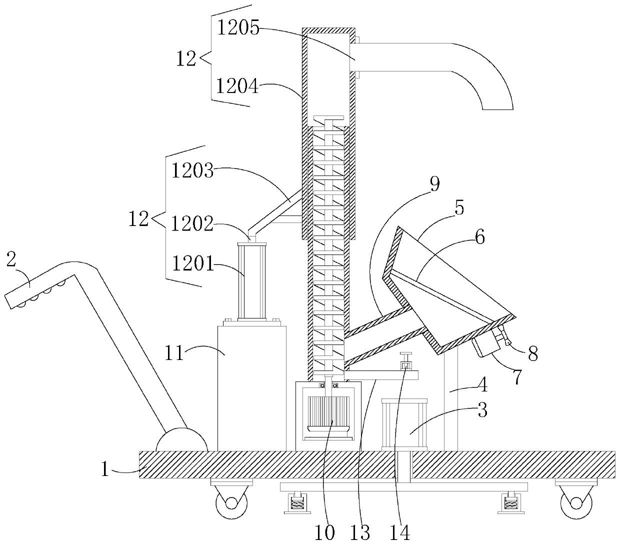
[0002] At present, the structure of the structural column pouring devices on the market is too simple, especially most of the existing structural column pouring devices are integrated with the car body, but the existing structural column pouring devices have poor positioning effect on the car body , this will cause the pouring device to shake to a certain extent when it is working. After a long period of shaking, the universal wheels at the bottom of the car body will cause certain damage to the ground, and the existing pouring device is constructed at a high place. When the column is poured, it is also necessary to manually install the connecting pipes, which will fully increase the labor intensity of the staff, and at the same time, fully reduce the work efficiency of the structural column pouring device

Method used


Image

  • Constructional column pouring device for buildings
  • Constructional column pouring device for buildings
  • Constructional column pouring device for buildings

Examples


Embodiment Construction

[0024] The materials, methods and instruments used in the following examples, unless otherwise specified, are conventional materials, methods and instruments in the art, and those of ordinary skill in the art can obtain them through commercial channels.

[0025] In the following description of the present invention, it should be noted that the terms "center", "longitudinal", "transverse", "upper", "lower", "front", "rear", "left", "right", The orientation or positional relationship indicated by "top", "bottom", "inner", "outer" and "vertical" are based on the orientation or positional relationship shown in the drawings, and are only for the convenience of describing the present invention and simplifying the description. It is not intended to indicate or imply that the referred device or element must have a particular orientation, be constructed in a particular orientation, and operate in a particular orientation, and thus should not be construed as limiting the invention.

[0...


PUM


Abstract

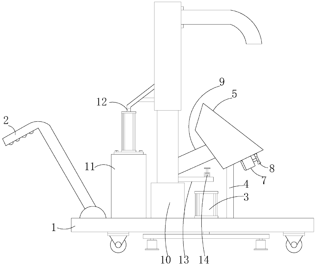
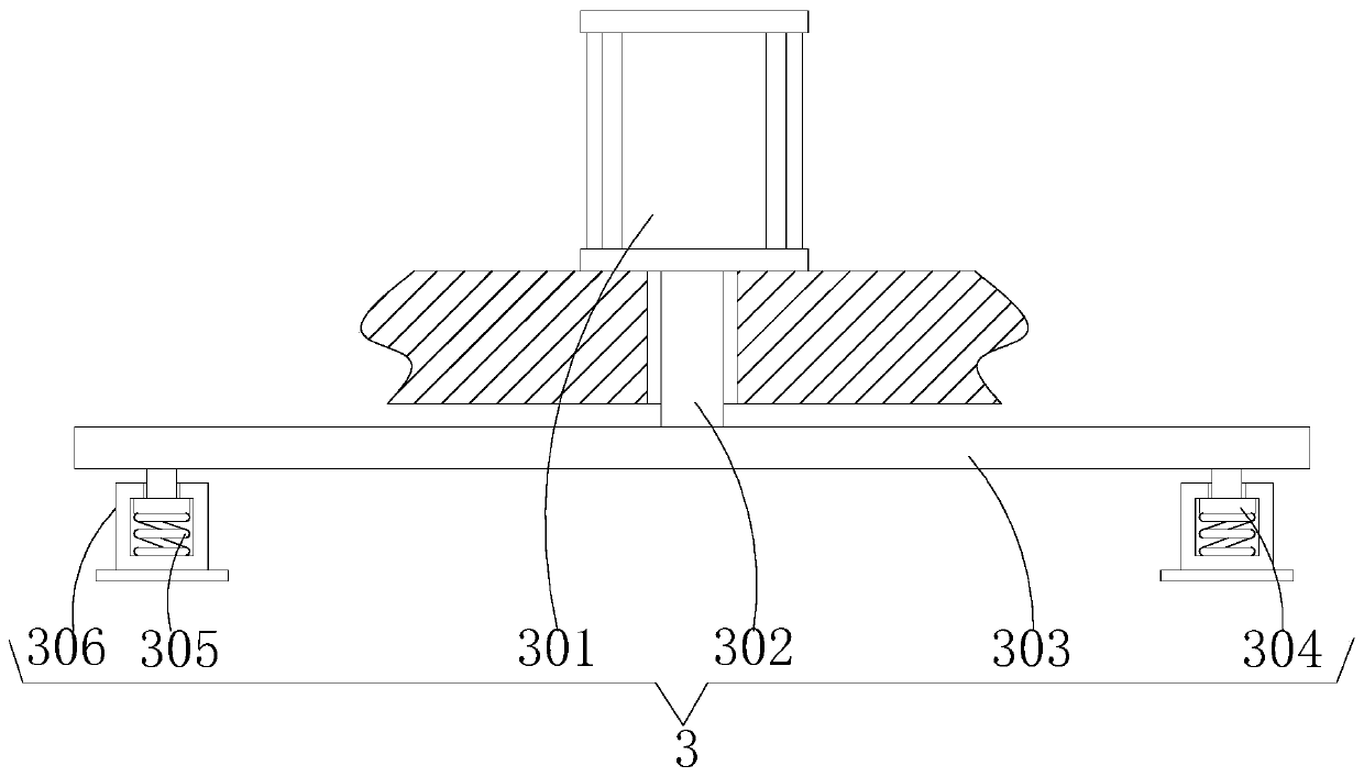
The invention discloses a constructional column pouring device for buildings, and relates to the technical field of building construction tools. The constructional column pouring device for buildingscomprises a cart body, a pushing handle, a stabilizing mechanism, a supporting rod, a feeding hopper, a screen, a first gear motor, a vibration rod, a material transport pipe, a feed mechanism, a control box and an expansion mechanism. The bottom end of the pushing handle is fixedly connected with the top surface of the left end of the vehicle body; the top end of the stabilizing mechanism is fixedly installed at the center of the top surface of the vehicle body; and the bottom end of the supporting rod is fixedly connected with the top surface of the right end of the vehicle body. The constructional column pouring device for buildings can quickly position the vehicle body; in this way, the stability of the whole pouring device can be fully improved; the pouring device is simple in structure and convenient to use, concrete can be rapidly fed, the material conveying speed of the pouring device can be increased, the height of a material conveying pipeline can be rapidly adjusted finally,the labor intensity of workers can be reduced, and therefore the working efficiency of the pouring device is further improved.

Description

technical field [0001] The invention relates to the technical field of building construction tools, in particular to a construction column pouring device for construction. Background technique [0002] At present, the structure of the structural column pouring devices on the market is too simple, especially most of the existing structural column pouring devices are integrated with the car body, but the existing structural column pouring devices have poor positioning effect on the car body , this will cause the pouring device to shake to a certain extent when it is working. After a long period of shaking, the universal wheels at the bottom of the car body will cause certain damage to the ground, and the existing pouring device is constructed at a high place. When the column is poured, it is also necessary to manually install the connecting pipes, which will fully increase the labor intensity of the staff, and at the same time, fully reduce the work efficiency of the construct...

Claims


Application Information

Patent Timeline
IPC IPC(8): E04G21/04
Inventor 王琪
Owner 王琪
Learn More