
Hydraulic cartridge valve

A cartridge valve and hydraulic technology, applied in the direction of fluid pressure actuators, servo motor components, mechanical equipment, etc., can solve the problems of difficult mass production of components, high requirements for coaxiality accuracy, and difficult processing, etc., to achieve a high degree of coordination The effect of reduced requirements, high interchangeability, and easy assembly

Pending Publication Date: 2019-05-21
DING SI SHANGHAI HYDRAULIC TECH CO LTD
View PDF1 Cites 0 Cited by
  • Summary
  • Abstract
  • Description
  • Claims
  • Application Information

AI Technical Summary

Problems solved by technology

[0003] The applicant provides a hydraulic cartridge valve with a reasonable structure in view of the shortcomings of the above-mentioned existing hydraulic cartridge valves, such as high coaxial precision requirements, difficult processing, difficult adjustment after manufacture, and non-standard components that are not easy to produce in batches. , can flexibly adjust the height of the cartridge valve when the fit is poor, and can also be combined to make cartridge valves of various height specifications. At the same time, it is easy to process and facilitate mass production

Method used


Image

  • Hydraulic cartridge valve
  • Hydraulic cartridge valve
  • Hydraulic cartridge valve

Examples


Embodiment Construction

[0023] The specific implementation manner of the present invention will be described below in conjunction with the accompanying drawings.

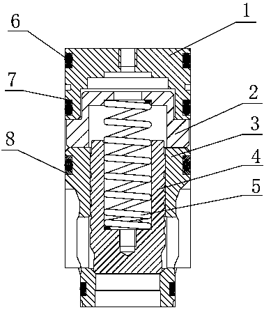
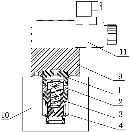
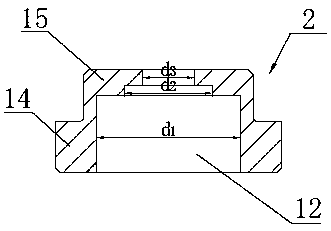
[0024] like figure 1 and figure 2 As shown, the hydraulic cartridge valve of the present invention is provided with a valve sleeve 3 at the lower part of the valve hole of the valve block 10, a sealing sleeve 1 is provided at the upper part of the valve hole, and a matching pad 2 is provided between the valve sleeve 3 and the sealing sleeve 1, The outer circumference of the sealing sleeve 1 is the same cylindrical surface, and the outer diameter of the cylindrical surface is basically the same as the maximum outer diameter of the valve sleeve 3 . A control cover plate 9 is arranged above the valve block 10 , and a counterbore is provided on the lower surface of the control cover plate 9 , and the upper part of the sealing sleeve 1 and the counterbore of the control cover plate 9 form a gap shaft hole for cooperation. A spool 4 is built ...


PUM


Abstract

The invention discloses a hydraulic cartridge valve, which is installed between a control cover plate and a valve block and comprises a valve sleeve, a valve core, a sealing sleeve and a return spring, wherein the periphery of the sealing sleeve is the same cylindrical surface, and the outer diameter of the cylindrical surface is basically consistent with the maximum outer diameter of the valve sleeve; clearance shaft hole cooperation is formed between the upper part of the sealing sleeve and the counterbore of the control cover plate, and between the lower part of the sealing sleeve and the valve hole of the valve block, and cylindrical surface sealing is arranged. According to the invention, the outer peripheral surface of the sealing sleeve is coaxially matched with the valve hole of the valve block and the counterbore of the control cover plate; the outer peripheral surfaces of the sealing sleeve and the valve sleeve are basically consistent, so coaxiality requirement is not increased, and manufacturing and assembling difficulties are reduced. In the invention, a plurality of groups of sealing rings are arranged on the outer peripherical surfaces of the sealing sleeve and the valve sleeve to form cylindrical sealing, so that oil leakage can be effectively prevented, the sealing effect is improved, and the requirement on the height fit of the sealing sleeve, the valve sleeveand the valve hole is reduced while the reliability of equipment is ensured.

Description

technical field [0001] The invention relates to the field of hydraulic valve equipment, in particular to a hydraulic cartridge valve. Background technique [0002] The cartridge valve is a composite valve that inserts the basic components of the valve into the valve hole of the valve block, and cooperates with the control cover plate and electromagnetic reversing valve to realize the flow or disconnection of the liquid circuit. It has the advantages of simple structure of the valve core, sensitive action, and good sealing performance Advantages, widely used in various hydraulic machinery. The Chinese utility model patent "201020680393.2---bonnet raised hydraulic cartridge valve" discloses a hydraulic cartridge valve consisting of a valve sleeve, valve core, valve cover, return spring, control cover plate and electromagnetic reversing valve. A valve core is arranged in the axial hole of the valve sleeve, a valve cover is sleeved on the upper end of the valve sleeve, and a re...

Claims


Application Information

Patent Timeline
IPC IPC(8): F15B13/02
Inventor 杨棋君
Owner DING SI SHANGHAI HYDRAULIC TECH CO LTD
Learn More