
Non-bearing independently driven electric axle

An independent drive, electric vehicle technology, applied in electric power units, axles, wheels, etc., can solve the problems of wheel-side motor and wheel-hub motor technical difficulty, direct-connected unsprung mass, high manufacturing cost, and improve acceleration. Effects of stable operability, reduced difficulty in manufacturing and assembly, and shortened manufacturing process

Pending Publication Date: 2019-01-29
HEFEI AAM AUTOMOBILE DRIVELINE & CHASSIS SYST
View PDF0 Cites 4 Cited by
  • Summary
  • Abstract
  • Description
  • Claims
  • Application Information

AI Technical Summary

Problems solved by technology

[0003] Aiming at the above problems, the present invention provides a non-load-bearing independent drive electric axle vehicle structure, which can not only solve the shortcomings of the central motor direct-connected type with too large unsprung mass and low transmission efficiency, but also optimize the wheel motor and hub motor Problems of high technical difficulty and high manufacturing cost, while improving serialization and modular design capabilities

Method used


Image

  • Non-bearing independently driven electric axle
  • Non-bearing independently driven electric axle
  • Non-bearing independently driven electric axle

Examples


Embodiment 1

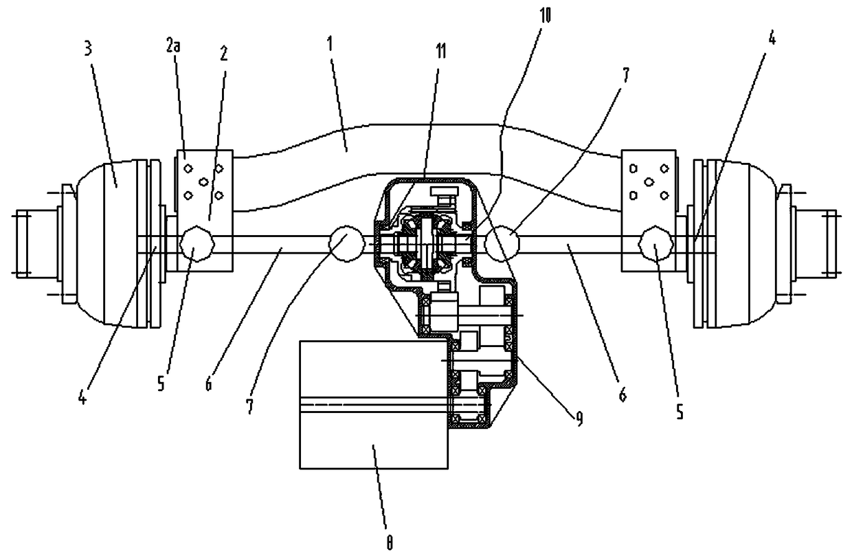
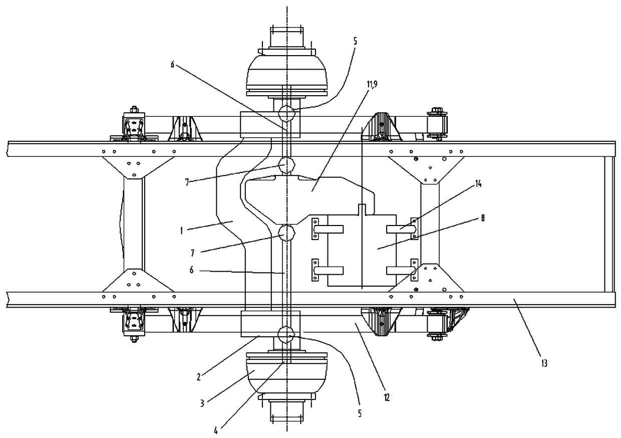
[0019] Such as figure 1 , figure 2 As shown, a non-load-bearing independent drive electric axle provided by the present invention includes a vehicle frame 13, a group of leaf springs 12 are respectively provided on both sides of the vehicle frame, and a wheel end connecting bracket 2 is respectively provided on both sides of the vehicle frame 13, Each wheel end connecting bracket 2 is respectively provided with a steel bracket 2a, and the steel bracket 2a is arranged at the position where the integral load-bearing axle housing 1 is connected with the wheel end connecting bracket 2, so that the integral load-bearing axle housing and the wheel end system The axis forms an offset setting, and the middle part of the integral load-bearing axle housing 1 is also provided with a concave structure for the differential 11 .

[0020] Each steel bracket 2a is connected to a corresponding group of leaf springs 12; each wheel end connecting bracket 2 is connected to the corresponding whe...

Embodiment 2

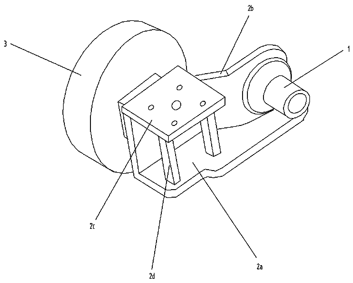
[0023] Such as image 3 As shown, the wheel end connection bracket 2 includes a bottom plate 2a and its connected vertical plate 2b, one side of the vertical plate 2b is connected to the wheel end system 3, and the other side is connected to the integral load-bearing axle housing 1, and the steel bracket 2a is arranged on the wheel end Where the system 3 is located, one side is connected to the vertical plate 2b, and the other side is connected to the bottom plate 2a by a set of columns 2d.

[0024] The invention can effectively reduce the unsprung mass of the whole vehicle, improve the acceleration and driving stability of the whole vehicle, and at the same time meet the load and transmission requirements of light commercial vehicles. The independent design is conducive to the implementation of product modularization. In terms of installation and maintenance, compared with the electric drive axle with a central motor direct-connection structure, it has huge application advant...


PUM


Abstract

The invention relates to a non-bearing independently driven electric vehicle axle. The non-bearing independently driven electric vehicle axle is characterized in that a steel bracket (2a) on each wheel end connection bracket (2) is connected with a corresponding steel plate spring on a vehicle frame; each wheel end connection bracket (2) is connected with a corresponding wheel end system (3), andthe two wheel end connection brackets are connected with an integral bearing axle shell (1) which deviates from the axis of the corresponding wheel end system; and the vehicle frame is fixedly connected with a drive motor (8), an integral structural gear box (9) and a differential mechanism (11), and first universal joints (7), oscillating half shafts (6), second universal joints (5) and hub shafts (4) are separately connected to two ends of the differential mechanism. The non-bearing independently driven electric vehicle axle is different from a common electric drive axle structure for a commercial light electric vehicle, an integrated independent electric drive structure and an integral bearing axle shell are adopted, the unsprung mass of a vehicle chassis is effectively reduced, the ground clearance of the electric drive axle is reduced, the advantages of convenient design, manufacture, installation, maintenance and the like are achieved, and in terms of cost economy, an independentsuspension structure with complex use and higher cost due to the use of independent drive is avoided.

Description

technical field [0001] The invention relates to a novel non-load-bearing independently driven electric vehicle axle. Background technique [0002] In recent years, due to the country's vigorous development of new energy vehicles, the application of electric drive axle products has developed rapidly. The biggest difference between the electric drive axle and the traditional axle is to change the transmission system and increase the motor and electronic control unit. For example, in the field of commercial vehicle integrated electric axle product development, the most common is the direct connection structure of the central motor on the traditional axle, which realizes the integration of the motor and the traditional axle, but the structure is large in size and under the leaf spring The quality is heavy, and the transmission efficiency is not high. The other is the wheel motor and the hub motor, both of which have canceled the axle housing and half shaft structure, but the m...

Claims


Application Information

Patent Timeline
IPC IPC(8): B60K1/00B60B35/12
CPCB60B35/12B60K1/00B60K2001/001
Inventor 宋力雄陈利张磊刘艳平邓树国何钦章
Owner HEFEI AAM AUTOMOBILE DRIVELINE & CHASSIS SYST
Learn More