Pneumatic atomization liquid-liquid injection method and machine capable of realizing large-scale variable working conditions

A technology of aerodynamic atomization and variable working conditions, which is applied in the direction of combustion method, burner, combustion type, etc., can solve problems such as poor atomization quality, and achieve the effect of reducing development cost and realizing large-scale variable thrust work.

Active Publication Date: 2019-05-21
XIAN AEROSPACE PROPULSION INST
View PDF4 Cites 10 Cited by
  • Summary
  • Abstract
  • Description
  • Claims
  • Application Information

AI Technical Summary

Problems solved by technology

[0003] The technical problem to be solved by the present invention is to provide a pneumatic atomization liquid injection method and injector that can realize a wide range of variable working conditions, so as to solve the problem of

Method used


Image

  • Pneumatic atomization liquid-liquid injection method and machine capable of realizing large-scale variable working conditions
  • Pneumatic atomization liquid-liquid injection method and machine capable of realizing large-scale variable working conditions

Examples


Example Embodiment

[0023] Embodiment one

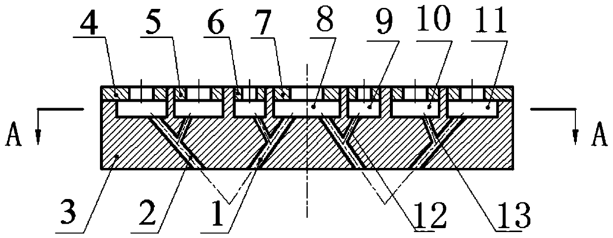
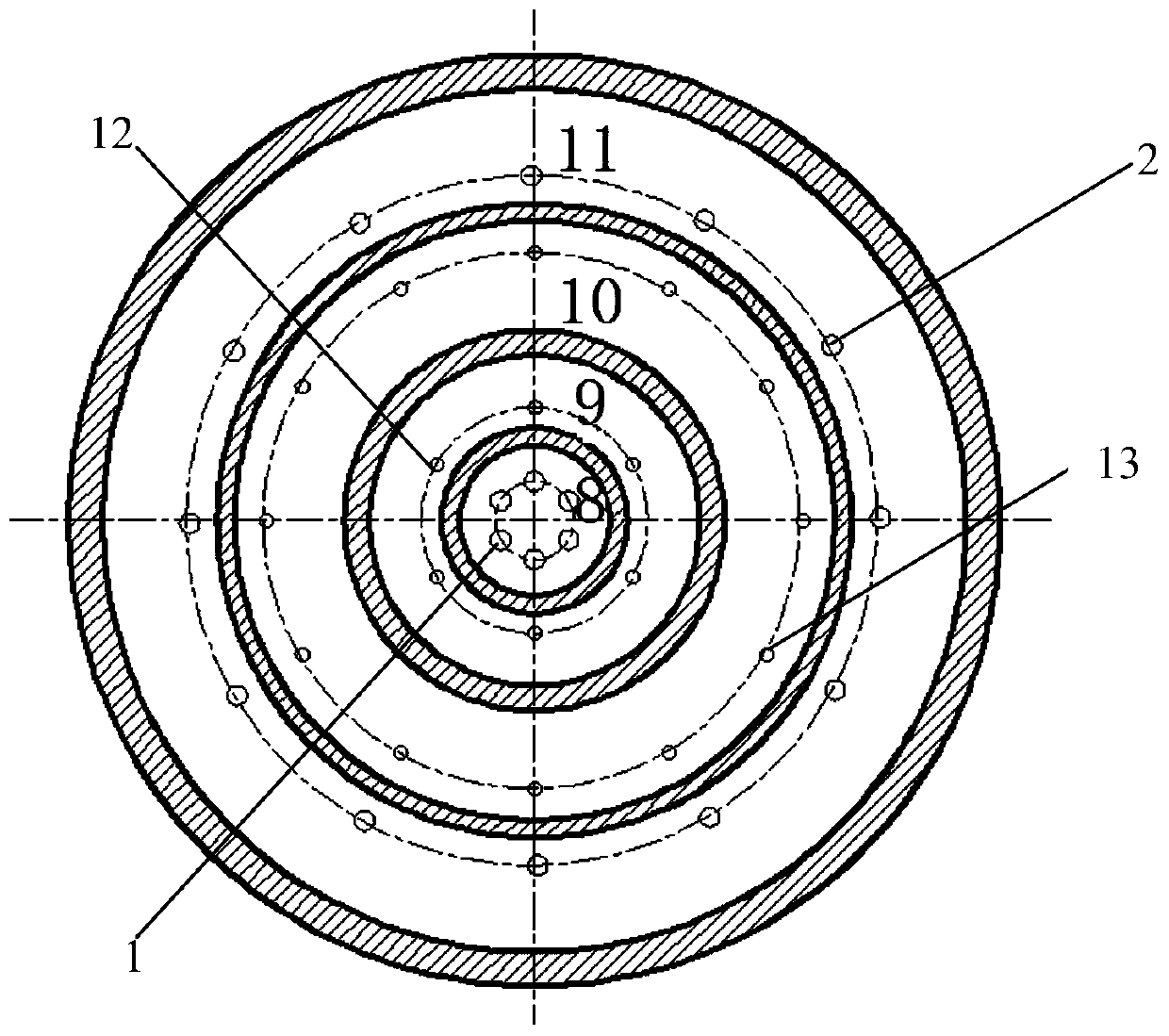
[0024] This embodiment takes n=2, m=1 as an example for illustration, as figure 1 As shown, the pneumatic atomizing liquid injector with a wide range of variable working conditions in this embodiment includes a spraying plate 3, grooves are provided on the upper end surface of the spraying plate 3, and each groove forms a first atomizing gas collection chamber 8 respectively. , the fuel collecting chamber 9, the oxidizing agent collecting chamber 10 and the second atomizing gas collecting chamber 11, the first atomizing gas collecting chamber 8 is located at the center of the upper end surface of the injection plate 3, the fuel collecting chamber 9, the oxidant collecting chamber The chamber 10 and the second atomizing gas collecting chamber 11 are annular chambers with the center of the first atomizing gas collecting chamber 8 as the center. In this embodiment, from the outermost circle to the center, there are the second atomized gas collecting chamb...

Example Embodiment

[0028] Embodiment two

[0029] When n>2, it is sufficient to continue to arrange corresponding chambers on the outer ring of the second atomizing gas collecting chamber 11 , and the fuel mist jet and the oxidant mist jet collide at one point through the corresponding atomizing gas nozzles.


PUM


Abstract

The invention discloses a pneumatic atomization liquid-liquid injection method and machine capable of realizing large-scale variable working conditions. The injection machine comprises an atomizing gas collecting cavity, a fuel liquid collecting cavity and an oxidizing agent liquid collecting cavity. Atomizing gas nozzles are formed in the bottom of the atomizing gas collecting cavity, and fuel nozzles and oxidizing agent nozzles are correspondingly formed in the bottom of the fuel liquid collecting cavity and the bottom of the oxidizing agent liquid collecting cavity. The outlet ends of the fuel nozzles and the outlet ends of the oxidizing agent nozzles correspondingly communicate with the middle sections of the different atomizing gas nozzles of the atomizing gas collecting cavity at a certain angle. Fuel mist jet flow and oxidizing agent mist jet flow are separately formed, and the fuel mist jet flow collides with the oxidizing agent mist jet flow at one point to further enhance atomization and mixing, and supporting conditions are provided for high quality combustion of fuel and an oxidizing agent.

Description

technical field [0001] The invention relates to a pneumatic atomized liquid injection method and an injector capable of realizing wide range variable working conditions. Background technique [0002] During the development of high Mach number and high-performance air-breathing engines, ground tests are required to simulate the ability of the engine inlet airflow to continuously change along the ballistic trajectory, which requires the heater of the ground test system to cover a wide range of flow rates and temperatures. At present, most of the injectors of the ground test system heaters use centrifugal nozzles to atomize the oxidant and fuel. The nozzles are pressure nozzles. When the flow rate changes in a large range, the pressure drop of the nozzle will become very high, which limits a single heater. The flow adjustment range (usually 2 to 3 times). Contents of the invention [0003] The technical problem to be solved by the present invention is to provide a pneumatic ...

Claims


Application Information

Patent Timeline
IPC IPC(8): F23D11/10F23D11/44F23D11/36F23D11/38
Inventor 吕发正熊剑高强肖虹李光熙房喜荣唐敏
Owner XIAN AEROSPACE PROPULSION INST
Why Eureka
Try Eureka