Photovoltaic module and manufacturing method thereof

A photovoltaic module and thickness direction technology, applied in the field of solar energy, can solve problems such as cell damage, achieve the effect of reducing the split rate and alleviating hard contact

Pending Publication Date: 2019-05-21
CSI CELLS CO LTD +2
View PDF6 Cites 16 Cited by
  • Summary
  • Abstract
  • Description
  • Claims
  • Application Information

AI Technical Summary

Problems solved by technology

In the above-mentioned traditional photovoltaic modules, since the ribbon needs to be pressed on the edge of the cell, and the contact between the ribbon and the edge of the cell is a hard contact, this brings a certain possibility of damage to the cell

Method used


Image

  • Photovoltaic module and manufacturing method thereof
  • Photovoltaic module and manufacturing method thereof
  • Photovoltaic module and manufacturing method thereof

Examples


no. 1 example

[0067] As a first embodiment, the method may include steps S1 and S2, wherein:

[0068] S1: A buffer layer is provided on the edge of the surface of the solar cell, and the surface is provided with electrodes.

[0069] S2: Connecting a plurality of solar cells into a string through welding ribbons, so that the buffer layer is located between the surface and the welding ribbons.

[0070] As a second embodiment, in order to obtain a laminated assembly, based on the content of the first embodiment above, the method further includes step S3:

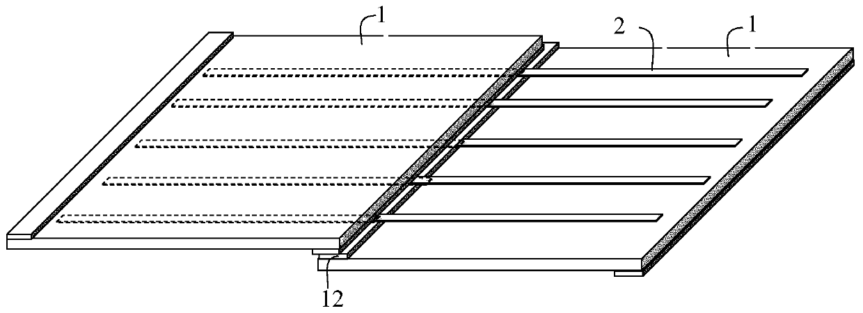
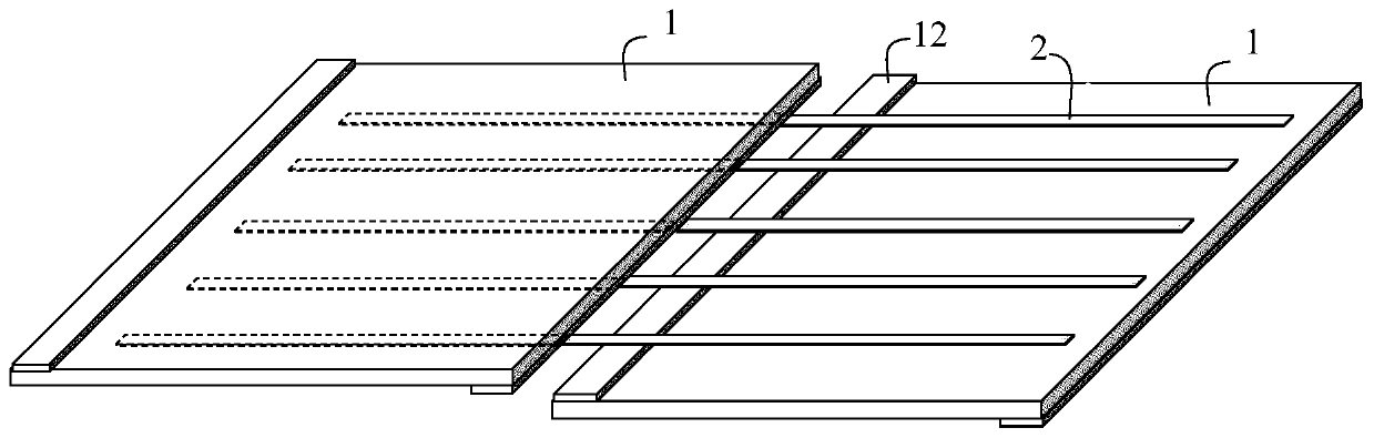
[0071] Edges of adjacent solar cells among the plurality of solar cells are overlapped to form an overlapping space between two adjacent solar cells.

[0072] As a third embodiment, in order to increase the module efficiency by reducing the area of ​​a single cell, it is necessary to divide cells of a conventional size, so based on the above second embodiment, step S1 may specifically include:

[0073] S101: Provide a first solar cell to b...

no. 4 example

[0078] As a fourth embodiment, a method for manufacturing a photovoltaic module includes steps S1 and S3, wherein:

[0079] S1: a buffer layer is provided on the edge of the surface of the solar cell, and the surface is provided with electrodes;

[0080] S3: connecting a plurality of solar cells into a string through welding ribbons, wherein the edges of adjacent solar cells in the plurality of solar cells are overlapped to form an overlap between two adjacent solar cells for the passage of the welding ribbons space, so that the buffer layer is located in the overlapping space and filled between two adjacent welding strips.

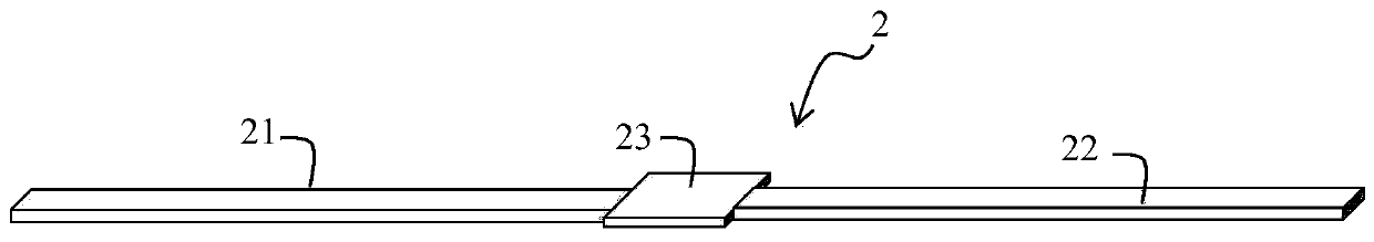
[0081] In a more specific embodiment, the ribbon includes a first section welded to the front electrode of the solar cell, a second section welded to the back electrode of another adjacent solar cell, and a connecting section connecting the first section and the second section. A transition section of the segment, the transition section is arranged in th...


PUM


Abstract

The embodiment of the invention provides a photovoltaic module and a manufacturing method thereof, wherein the photovoltaic module comprises several battery strings; the battery string comprises several solar batteries, a solder strip and a buffer layer; the solder strip is used for connecting adjacent two solar batteries, so that the several solar batteries are connected into a string; and the buffer layer can be arranged at the edge of the solar battery crossed with the solder strip, and positioned between the surface of the solar battery with an electrode and the solder strip.

Description

technical field [0001] The invention relates to the field of solar energy, in particular to a photovoltaic module and a manufacturing method thereof. Background technique [0002] In a traditional photovoltaic module, the solar cells are connected to each other by a ribbon, so that one end of the ribbon is connected to one electrode of the solar cell, and the other end is connected to the other electrode of the adjacent solar cell, thus forming a battery series connection. . In the traditional photovoltaic modules mentioned above, since the solder ribbon needs to be pressed against the edge of the cell, and the contact between the solder ribbon and the edge of the cell is a rigid contact, this brings a certain possibility of damage to the cell. Contents of the invention [0003] The object of the present invention is to provide a photovoltaic module and a manufacturing method thereof. [0004] In order to achieve the above purpose, the embodiment of the present invention...

Claims


Application Information

Patent Timeline
Patent Type & Authority Applications(China)
IPC IPC(8): H01L31/05H01L31/0216H01L31/18
CPCY02E10/50Y02P70/50
Inventor 潘秀娟黄甫阳董经兵刘亚锋邢国强
Owner CSI CELLS CO LTD
Why Eureka
Try Eureka