Network port component for network communication equipment

A technology for network communication and equipment, applied in the field of network port components for network communication equipment, can solve problems such as corrosion of interface chips, poor contact of network cable access network ports, and communication network equipment not working properly, so as to prevent dead ends and improve effective sexual effect

Active Publication Date: 2021-08-31
JIANGSU KECHUANG TRAFFIC SAFETY IND RES INST CO LTD
View PDF6 Cites 0 Cited by
  • Summary
  • Abstract
  • Description
  • Claims
  • Application Information

AI Technical Summary

Problems solved by technology

[0003] It also needs to be applied to communication network equipment in large-scale production workshops. When communication network equipment is working, some network ports will be in an idle state. Because there is a lot of dust in the environment of large-scale production workshops, and the access of network ports is in an exposed environment, dust accumulates in the environment. In the network port, the chip components of the network port are oxidized and corroded due to the adhesion of dust, resulting in poor contact when the network cable is connected to the network port, and the network port cannot be used normally. Carry out regular cleaning, but due to the semi-closed design of the network port, the dust attached to the side wall of the network port and the network port chip is difficult to clean, and the interface chip will still be corroded by the residual dust on the side wall of the network port and the network port chip , resulting in poor contact when the network cable is connected to the network port, and the communication network equipment cannot work normally.

Method used


Image

  • Network port component for network communication equipment
  • Network port component for network communication equipment
  • Network port component for network communication equipment

Examples


Embodiment Construction

[0028] In order to make the technical means, creative features, goals and effects achieved by the present invention easy to understand, the present invention will be further described below in conjunction with specific embodiments.

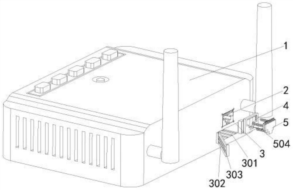
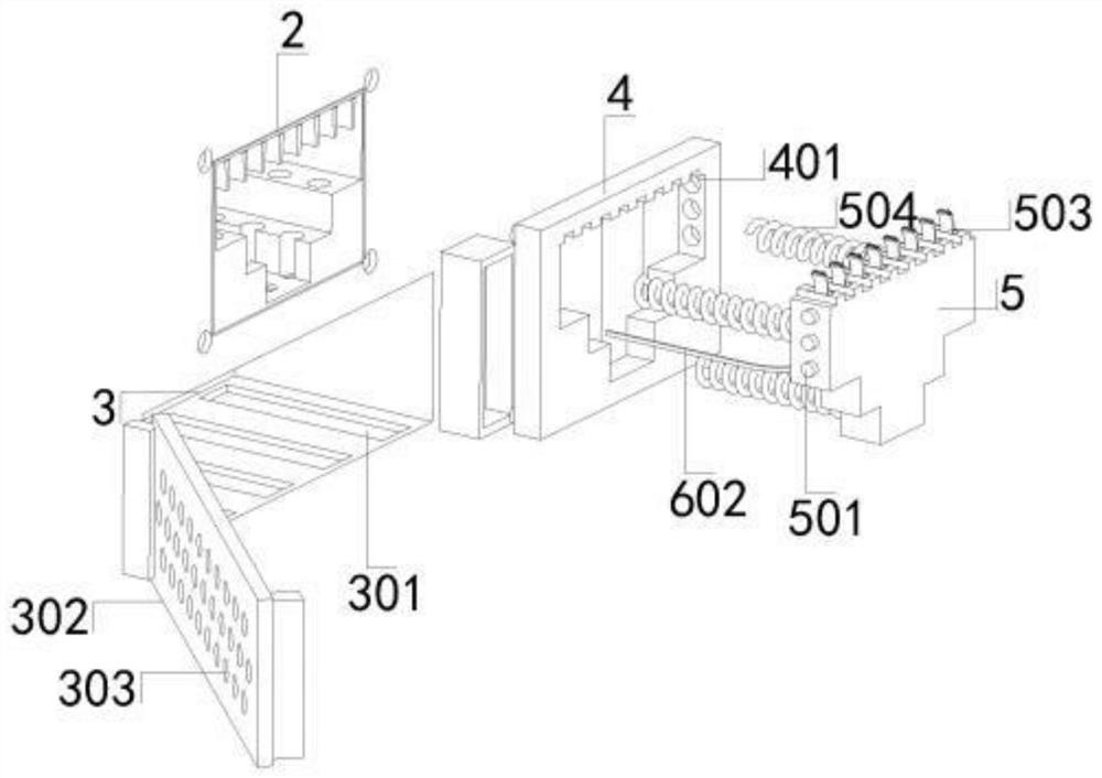
[0029] Such as Figure 1 to Figure 6 As shown, a network port assembly for network communication equipment includes a network communication device 1 and a network port access port 2. A dust collection tank 3 located under the chip board in the network communication device 1 is provided directly below the network port access port 2. And the network end inlet 2 is provided with a guide flow hole that connects the network end inlet 2 with the inner cavity of the dust collection tank 3, and the dust collection tank 3 communicates with the bottom of the network end inlet 2 through the through groove on the top side The bottom of the inner cavity of the dust collection tank 3 is provided with an electrostatic tank plate 301, and one side of the front of...


PUM


Abstract

The invention belongs to the technical field of network equipment, and specifically relates to a network port assembly for network communication equipment, including network communication equipment and a network terminal access port. A chip board located in the network communication device is provided directly below the network terminal access port. The dust collection tank below, the dust collection tank is connected with the bottom of the net end inlet through the through groove on the top side, and the bottom of the inner cavity of the dust collection tank is provided with an electrostatic slot plate. In the present invention, through the combined action of the external cover plate and the parts on the receiving push plate, the receiving push plate can absorb, brush and clean the dust on the chip during the passive moving process of the push plate, and the dust on the dust removal brush can be cleaned. During the adsorption process, through the combined action of the dust removal brush and the movable groove, the dust on the dust removal brush enters the receiving push plate along the spiral groove in the dust removal brush through the movable groove, so as to ensure the dust on the dust removal brush during the movement of the dust removal brush. The dust has the function of falling, so that the dust removal brush has the function of continuously absorbing, brushing and cleaning the dust.

Description

technical field [0001] The invention belongs to the technical field of network equipment, in particular to a network port assembly for network communication equipment. Background technique [0002] The traditional communication network is composed of three parts: transmission, switching and terminal. Through specific equipment, people can communicate and transmit information through the media. Communication network equipment usually has multiple network ports. At the same time, in order to increase The heat dissipation effect of the network port, the network port is usually in a semi-open state. [0003] It also needs to be applied to communication network equipment in large-scale production workshops. When communication network equipment is working, some network ports will be in an idle state. Because there is a lot of dust in the environment of large-scale production workshops, and the access of network ports is in an exposed environment, dust accumulates in the environmen...

Claims


Application Information

Patent Timeline
Patent Type & Authority Patents(China)
IPC IPC(8): H04L12/02B08B1/00B08B6/00
Inventor 杨美华其他发明人请求不公开姓名
Owner JIANGSU KECHUANG TRAFFIC SAFETY IND RES INST CO LTD
Why Eureka
Try Eureka