Camera assembly, electronic equipment and control method of camera assembly

A technology for a camera assembly and an imaging assembly, applied in the field of photography, can solve the problems of increasing the cost of the camera, and the structure is not integrated.

Inactive Publication Date: 2019-05-21
GUANGDONG OPPO MOBILE TELECOMM CORP LTD
View PDF6 Cites 13 Cited by
  • Summary
  • Abstract
  • Description
  • Claims
  • Application Information

AI Technical Summary

Problems solved by technology

[0004] In the existing solution, the front camera assembly and the rear camera assembly are designed separately, and the structure is not integrated. They need to be molded separately during production and processing. T

Method used


Image

  • Camera assembly, electronic equipment and control method of camera assembly
  • Camera assembly, electronic equipment and control method of camera assembly
  • Camera assembly, electronic equipment and control method of camera assembly

Examples


Embodiment 1

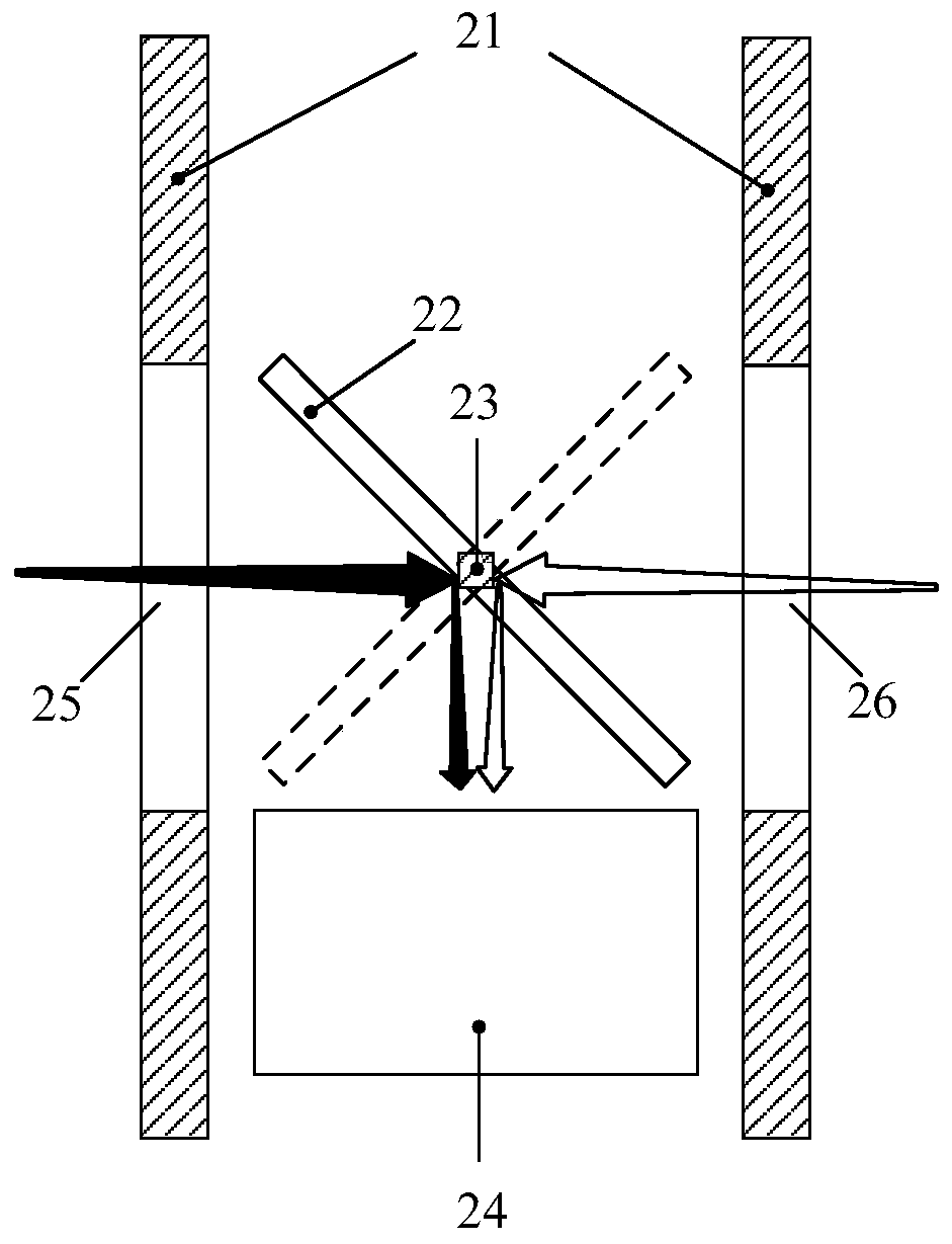
[0020] like figure 2 As shown, the camera assembly includes: a housing 21, a reflection assembly 22, a driving assembly 23 and an imaging assembly 24;

[0021] The casing 21 is provided with a first light-transmitting component 25 and a second light-transmitting component 26 facing oppositely and center-aligned; the drive component 23 drives the reflective component 22 to rotate around the rotation axis, so that the reflective component 22 switch between the first position and the second position;

[0022] The reflective component 22 is in the first position, and the reflective surface of the reflective component 22 reflects the first ambient light passing through the first light-transmitting component 25 to the imaging component 24;

[0023] The reflective component 22 is in the second position, and the reflective surface of the reflective component 22 reflects the second ambient light passing through the second light-transmitting component 26 to the imaging component 24 . ...

Embodiment 2

[0075] An embodiment of the present application also provides a method for controlling a camera assembly, where the camera assembly includes: a housing, a reflection assembly, a driving assembly, and an imaging assembly;

[0076] The casing is provided with a first light-transmitting component and a second light-transmitting component facing opposite and aligned in the center; the driving component drives the reflecting component to rotate around the rotation axis, so that the reflecting component is in the first position and the second light-transmitting component Switch between locations;

[0077] The methods include:

[0078] controlling the reflective component to be in the first position, so that the reflective surface of the reflective component reflects the first ambient light passing through the first light-transmitting component to the imaging component;

[0079] Alternatively, the reflective component is controlled to be at the second position, so that the reflectiv...


PUM


Abstract

The embodiment of the invention discloses a camera assembly, and is characterized in that the camera assembly comprises a housing, a reflection assembly, a driving assembly, and an imaging assembly; The shell is provided with a first light-transmitting assembly and a second light-transmitting assembly which are opposite in orientation and are aligned in the center. The driving assembly drives thereflecting assembly to rotate around a rotating shaft, so that the reflecting assembly is switched between a first position and a second position; The reflection assembly is located at a first position, and the reflection surface of the reflection assembly reflects the first ambient light passing through the first light transmission assembly to the imaging assembly; The reflection assembly is located at a second position, and the reflection surface of the reflection assembly reflects the second ambient light passing through the second light transmission assembly to the imaging assembly. The embodiment of the invention further discloses electronic equipment comprising the camera assembly and a control method of the camera assembly.

Description

technical field [0001] The present application relates to camera technology, and in particular to a camera assembly, electronic equipment and a control method for the camera assembly. Background technique [0002] The camera assembly is an important part of the mobile terminal, and generally consists of a lens, a photosensitive chip sensor (sensor), a focus motor, and a printed circuit board (Printed Circuit Board, PCB). According to the different shooting objects of the mobile terminal, the camera is divided into a front camera and a rear camera. The front camera is generally used for Selfie, video call, etc., and the rear camera is generally used for shooting other scenes. At present, the camera components are matched with lenses and sensors one by one, and one lens is imaged on one sensor. The overall trend of mobile terminal cameras is towards miniaturization on the premise of ensuring image quality. It is of great significance to reduce the cost of camera components wh...

Claims


Application Information

Patent Timeline
IPC IPC(8): H04N5/225H04M1/02
Inventor 林俊国
Owner GUANGDONG OPPO MOBILE TELECOMM CORP LTD
Why Eureka
Try Eureka