Camera mechanism and electronic device

A technology of imaging components and light-transmitting areas, applied in the field of photography, can solve problems such as camera limitations, and achieve the effect of reducing limitations, maintaining camera quality, and reducing occupied space

Inactive Publication Date: 2020-11-03
OPPO CHONGQING INTELLIGENT TECH CO LTD
View PDF6 Cites 0 Cited by
  • Summary
  • Abstract
  • Description
  • Claims
  • Application Information

AI Technical Summary

Problems solved by technology

At present, due to the thin and light design of mobile phones, ther...

Method used


Image

  • Camera mechanism and electronic device
  • Camera mechanism and electronic device
  • Camera mechanism and electronic device

Examples


Embodiment Construction

[0022] Embodiments of the present application are described in detail below, examples of which are shown in the drawings, wherein the same or similar reference numerals denote the same or similar elements or elements having the same or similar functions throughout. The embodiments described below by referring to the drawings are exemplary, are only for explaining the embodiments of the present application, and should not be construed as limiting the embodiments of the present application.

[0023] The structure of the camera mechanism according to the embodiment of the present application will be described below with reference to the drawings.

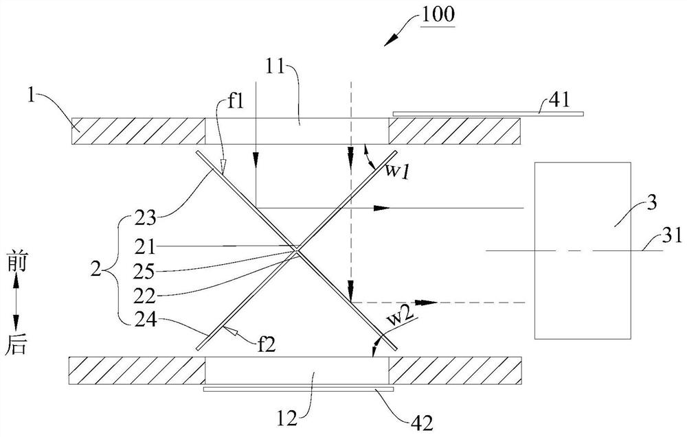
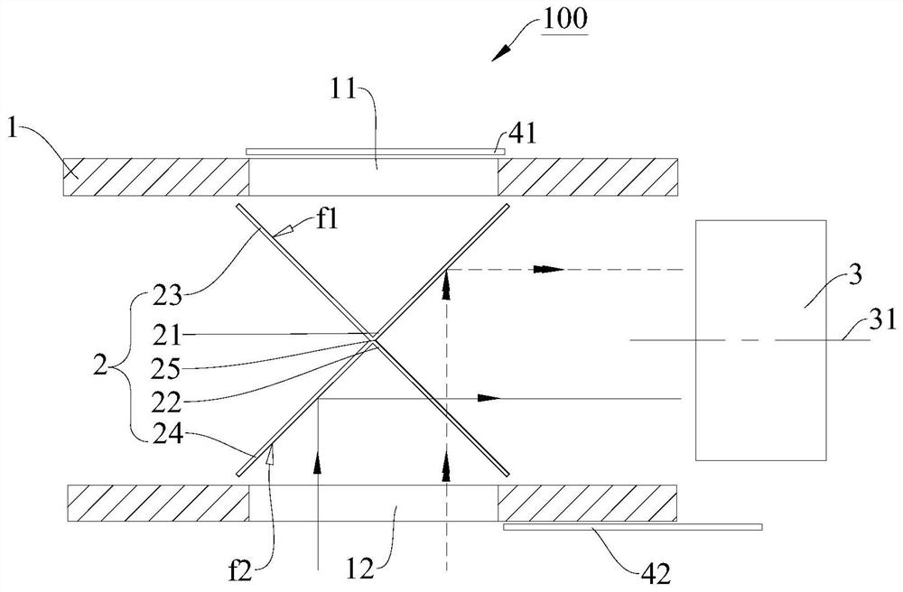
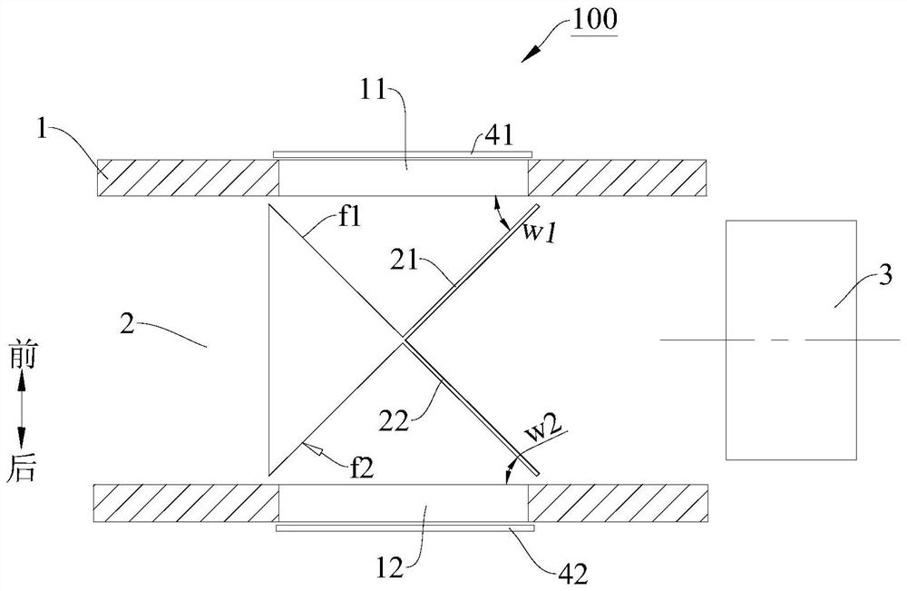
[0024] A camera mechanism 100 according to the present application, such as figure 1 with figure 2 As shown, it includes: a casing 1 , an optical path conversion component 2 and an imaging component 3 . A first light-transmitting area 11 and a second light-transmitting area 12 are respectively provided on the opposite side walls of ...


PUM


Abstract

The invention discloses a camera mechanism and electronic equipment. The camera mechanism comprises a shell, a light path conversion assembly and an imaging assembly. A first light-transmitting area and a second light-transmitting area are arranged on the two sides of the shell. The light path conversion assembly comprises a first transflective mirror, a second transflective mirror, a first reflecting surface and a second reflecting surface. When light enters the first light-transmitting area, part of the light is reflected by the first reflecting surface and then penetrates through the firsttransflective mirror to be emitted to the imaging assembly, and part of the light penetrates through the first light-transmitting mirror and then is reflected by the second light-transmitting mirror to the imaging assembly. When light enters the second light-transmitting area, part of the light is reflected from the second reflecting surface and then penetrates through the second transflective mirror to be emitted to the imaging assembly, and part of the light penetrates through the second light-transmitting mirror and then is reflected to the imaging assembly through the first light-transmitting mirror. The camera mechanism can effectively control the cost and the occupied space, the image photographing quality can be easily maintained after long-term use, and the limitation on the imaging assembly can be reduced.

Description

technical field [0001] The present application relates to camera technology, in particular to a camera mechanism and electronic equipment. Background technique [0002] Nowadays, electronic devices such as mobile phones and palm treasures have become a necessity in people's lives, and selfies have gradually become an indispensable part of people's lives. At present, due to the thin and light design of mobile phones, there are many restrictions on the camera, which urgently needs to be improved. Contents of the invention [0003] In order to solve the above technical problems, the embodiment of the present application expects to provide a camera mechanism and electronic equipment. [0004] The embodiment of the present application provides a camera mechanism, including: a housing, a first light-transmitting area and a second light-transmitting area are respectively arranged on opposite side walls of the housing; In the housing, the optical path conversion assembly is loca...

Claims


Application Information

Patent Timeline
IPC IPC(8): H04N5/225H04M1/02
CPCH04M1/0264H04N23/51H04N23/57H04N23/55
Inventor 张凯朋
Owner OPPO CHONGQING INTELLIGENT TECH CO LTD
Why Eureka
Try Eureka