Cooling device for image processing equipment

A technology of image processing equipment and heat dissipation device, applied in the direction of cooling/ventilation/heating transformation, etc., can solve the problems of no water cooling heat dissipation device and low heat dissipation efficiency.

Inactive Publication Date: 2019-05-21
BEIHUA UNIV
View PDF4 Cites 4 Cited by
  • Summary
  • Abstract
  • Description
  • Claims
  • Application Information

AI Technical Summary

Problems solved by technology

[0002] For example, the patent number is CN201820472691.9, a cooling device for electronic and electrical equipment, including a box body, a heat absorption fan is provided on the left side of the box body, and a heat absorption pipe is provided on the right side of the heat absorption fan. Both the top and the bottom of the heat fan are provided with a motor, the left side of the motor is provided with a heat insulation layer, and the left side of the heat insulation board is provided with a rotating shaft, and the rotating shaft is electrically connected with the output end of the motor, so The left side of the rotating shaft is connected to the cold tank provided in the inner cavity of the condensed water layer, and the cold tank is provided with a plurality of water stirring plates of uniform size, but the disadvantage of this invention is that there is no water cooling device, and only the air is used to dissipate heat. , the heat dissipation efficiency is relatively low

Method used


Image

  • Cooling device for image processing equipment
  • Cooling device for image processing equipment
  • Cooling device for image processing equipment

Examples


specific Embodiment approach 1

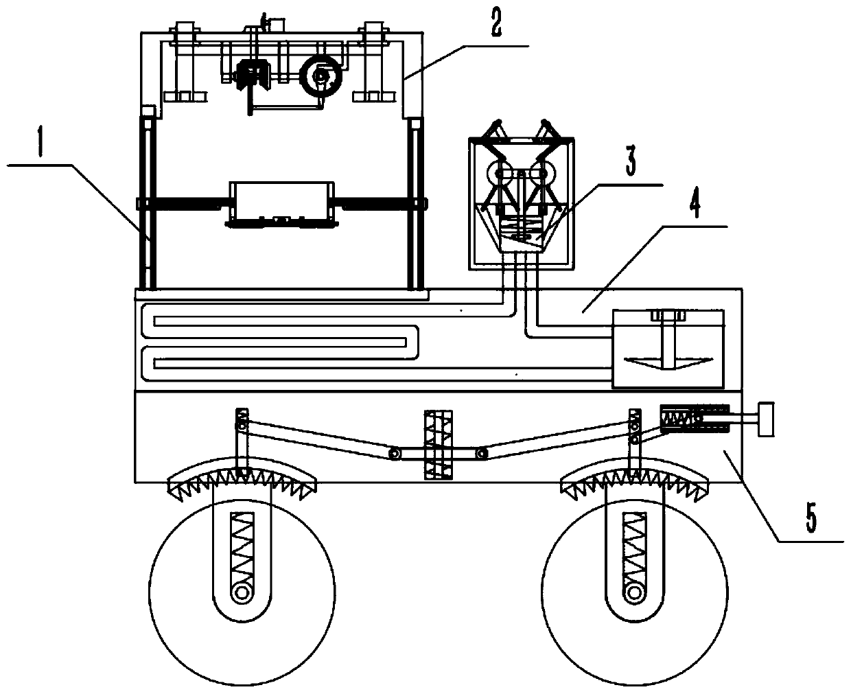
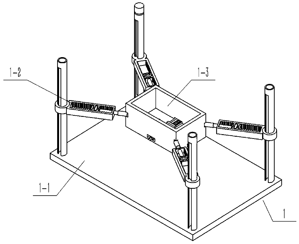
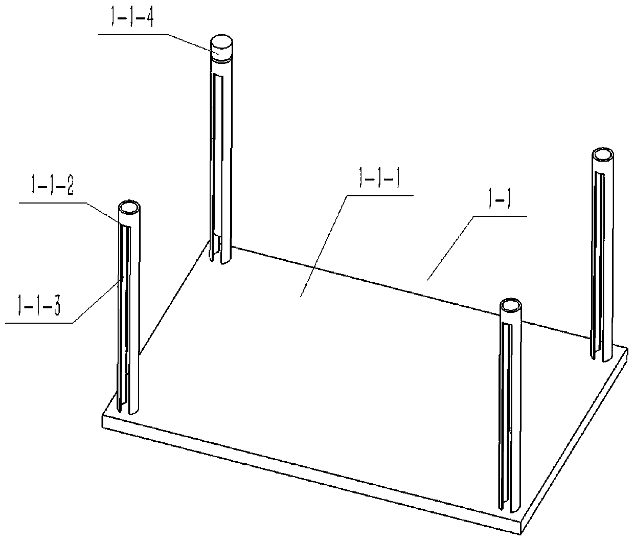
[0040] Combine below Figure 1-21 Describe this embodiment, a heat dissipation device for image processing equipment, including a bracket assembly 1, an air cooling structure 2, a water exchange box 3, a water cooling box 4, a support frame assembly 5 and a shock absorber 6, the bracket assembly 1 includes the support bottom plate 1-1, the telescopic sliding column 1-2 and the installation frame 1-3, the support bottom plate 1-1 includes the support bottom plate body 1-1-1, four side wall sliding columns 1-1-2, four A hollow sliding cavity 1-1-3 and a rotating threaded rod 1-1-4, and four side wall sliding columns 1-1-2 are respectively fixedly connected to the four corners of the upper end surface of the bracket bottom plate body 1-1-1 , the four hollow sliding chambers 1-1-3 are respectively arranged on the inner ends of the four side wall sliding columns 1-1-2, and the rotating threaded rod 1-1-4 is connected to the side wall sliding column 1-1-2 Upper end; telescopic slid...

specific Embodiment approach 2

[0049] Combine below Figure 1-21 Describe this embodiment, and this embodiment will further explain Embodiment 1. There are four telescopic connecting rods 1-2-3, and the four telescopic connecting rods 1-2-3 can facilitate the installation of the outer frame 1-3. stability.

specific Embodiment approach 3

[0050] Combine below Figure 1-21 This embodiment will be described, and this embodiment will further describe the first embodiment, the inner push spring 5-16 is in a compressed state.


PUM


Abstract

The invention relates to a cooling device, in particular to a cooling device for image processing equipment. According to the cooling device, the using height of a bracket combination can be conveniently adjusted through a rotary threaded rod, so that the air cooling effect can be conveniently adjusted; the air flow can be accelerated through an air cooling structure, so that the cooling effect can be conveniently improved; water circulation-based heat exchange in a water cooling tank can be realized through the water exchange tank, so that the cooling is accelerated; and the using position ofthe device can be conveniently adjusted through a support frame combination. The device comprises the bracket combination, the air cooling structure, the water exchange tank, the water cooling tank,the support frame combination and a damper; through threaded connection between the rotary threaded rod and two inner-end bosses, the two inner-end bosses drive a flexible outer frame body to move upand down along a hollow sliding cavity; through connection between four flexible sliding columns and a mounting outer frame, the distance between the mounting outer frame and a bracket bottom plate body can be adjusted; and flexible connection rods can conveniently connect the flexible sliding columns with the mounting outer frame.

Description

technical field [0001] The invention relates to a heat dissipation device, more specifically to a heat dissipation device of an image processing device. Background technique [0002] For example, the patent number is CN201820472691.9, a cooling device for electronic and electrical equipment, including a box body, a heat absorption fan is provided on the left side of the box body, and a heat absorption pipe is provided on the right side of the heat absorption fan. Both the top and the bottom of the heat fan are provided with a motor, the left side of the motor is provided with a heat insulation layer, and the left side of the heat insulation board is provided with a rotating shaft, and the rotating shaft is electrically connected with the output end of the motor, so The left side of the rotating shaft is connected to the cold tank provided in the inner cavity of the condensed water layer, and the cold tank is provided with a plurality of water stirring plates of uniform size,...

Claims


Application Information

Patent Timeline
Patent Type & Authority Applications(China)
IPC IPC(8): H05K7/20
Inventor 毕馨文徐彬斌
Owner BEIHUA UNIV
Why Eureka
Try Eureka