Temporary marking machine for stadiums

A technology for stadiums and scribing machines, used in water skiing, sports accessories, ice skating, etc., can solve the problems of trouble, crooked walking, and high labor costs

Active Publication Date: 2019-05-24
ANHUI QIANTONG EDUCATION MFG
View PDF8 Cites 2 Cited by
  • Summary
  • Abstract
  • Description
  • Claims
  • Application Information

AI Technical Summary

Problems solved by technology

[0002] A large number of games will be held on the stadium, but the starting point of the game will be marked with a starting line, so that everyone's starting point is consistent without affecting the fairness of the game. Usually, people use lime powder to draw the line, because people move There will be a phenomenon of crookedness, which will easily lead to the bending of the drawn line and affect the u...

Method used


Image

  • Temporary marking machine for stadiums
  • Temporary marking machine for stadiums
  • Temporary marking machine for stadiums

Examples


Embodiment 1

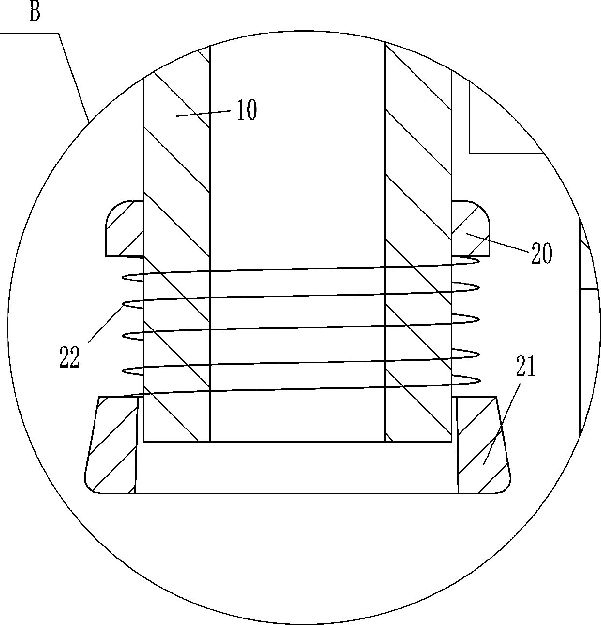
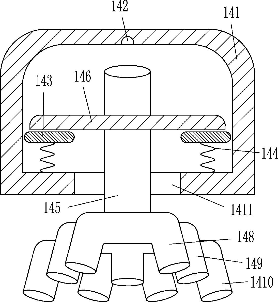
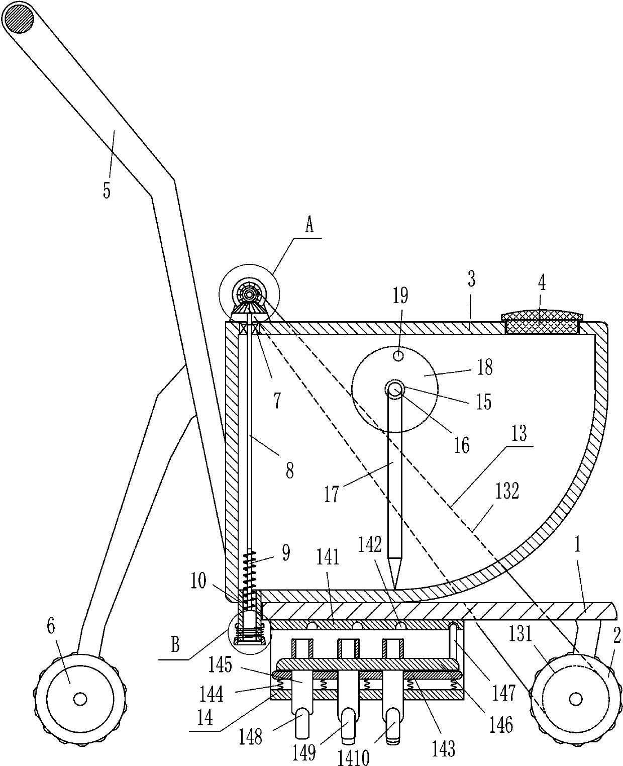
[0022] A temporary marking machine for stadiums, such as Figure 1-4 As shown, it includes a bottom plate 1, a first roller 2, a placement frame 3, a plug 4, a push handle 5, a second roller 6, a first bearing seat 7, a rotating shaft 8, a screw conveying shaft 9, a discharge pipe 10, and a first cone. Gear 11, second bevel gear 12 and transmission mechanism 13, the first roller 2 is installed on the bottom right side of the bottom plate 1, the placement frame 3 that can store lime powder is installed on the left side of the top of the bottom plate 1, and the top right side of the placement frame 3 is provided with The plug 4 and the first bearing seat 7 are embedded and installed on the left side of the top of the placement frame 3. The rotating shaft 8 is connected with the bearing in the first bearing seat 7. The top of the rotating shaft 8 is fixedly connected with the first bevel gear 11, which can be used for lime powder. The conveying screw conveying shaft 9 is installe...

Embodiment 2

[0024] A temporary marking machine for stadiums, such as Figure 1-4As shown, it includes a bottom plate 1, a first roller 2, a placement frame 3, a plug 4, a push handle 5, a second roller 6, a first bearing seat 7, a rotating shaft 8, a screw conveying shaft 9, a discharge pipe 10, and a first cone. Gear 11, second bevel gear 12 and transmission mechanism 13, the first roller 2 is installed on the bottom right side of the bottom plate 1, the placement frame 3 that can store lime powder is installed on the left side of the top of the bottom plate 1, and the top right side of the placement frame 3 is provided with The plug 4 and the first bearing seat 7 are embedded and installed on the left side of the top of the placement frame 3. The rotating shaft 8 is connected with the bearing in the first bearing seat 7. The top of the rotating shaft 8 is fixedly connected with the first bevel gear 11, which can be used for lime powder. The conveying screw conveying shaft 9 is installed...

Embodiment 3

[0027] A temporary marking machine for stadiums, such as Figure 1-4 As shown, it includes a bottom plate 1, a first roller 2, a placement frame 3, a plug 4, a push handle 5, a second roller 6, a first bearing seat 7, a rotating shaft 8, a screw conveying shaft 9, a discharge pipe 10, and a first cone. Gear 11, second bevel gear 12 and transmission mechanism 13, the first roller 2 is installed on the bottom right side of the bottom plate 1, the placement frame 3 that can store lime powder is installed on the left side of the top of the bottom plate 1, and the top right side of the placement frame 3 is provided with The plug 4 and the first bearing seat 7 are embedded and installed on the left side of the top of the placement frame 3. The rotating shaft 8 is connected with the bearing in the first bearing seat 7. The top of the rotating shaft 8 is fixedly connected with the first bevel gear 11, which can be used for lime powder. The conveying screw conveying shaft 9 is installe...


PUM


Abstract

The invention relates to a marking machine, in particular to a temporary marking machine for stadiums. The technical problem of the invention is to provide a temporary marking machine for stadiums, which has no need for a user to make markings with limestone powder, which prevents bending of markings from affecting usage, which allows multiple markings to be made at the same time, and which has high working efficiency. The temporary marking machine for stadiums comprises a bottom plate, a first roller, a holding basket, a piston, a push handle, a second roller, a first bearing block, a spindle, a screw conveyer shaft, a discharge pipe, a first bevel gear and the like; the first roller is mounted on the right of the bottom of the bottom plate; the holding basket to store limestone powder may be mounted on the left of the top of the bottom plate; the piston is arranged on the right side of the top of the holding basket. The limestone powder is poured into the holding basket; the machineherein is pushed to move at a marking position; the limestone power falls on the marking position to form a marking; holding the limestone powder manually to make markings is not required; it is prevented that bending of the markings affects usage.

Description

technical field [0001] The invention relates to a marking machine, in particular to a temporary marking machine for stadiums. Background technique [0002] A large number of games will be held on the stadium, but the starting point of the game will be marked with a starting line, so that everyone's starting point is consistent without affecting the fairness of the game. Usually, people use lime powder to draw the line, because people move There will be a phenomenon of crookedness, which will easily lead to the bending of the drawn line and affect the use, and when multiple lines need to be drawn, people need to bend over constantly, which is easy to cause low back pain and affect work efficiency, so people will use straight tools to place them in the marking position Besides, people draw lines along the tool to avoid bending, and when multiple lines need to be melted, multiple people draw lines at the same time, so it is troublesome and the labor cost is high. Contents of ...

Claims


Application Information

Patent Timeline
IPC IPC(8): A63C19/08
Inventor 曾椿洋
Owner ANHUI QIANTONG EDUCATION MFG
Why Eureka
Try Eureka