Small unpowered unmanned aerial vehicle mounting device

A UAV mounting and UAV technology, which is applied in the direction of launching devices, aircraft parts, transportation and packaging, etc., can solve the problems of small number of mounts, heavy weight, complex structure, etc., and achieve high space utilization efficiency and design Simple, Small Effects

Active Publication Date: 2019-05-24
XIJING UNIV
View PDF6 Cites 2 Cited by
  • Summary
  • Abstract
  • Description
  • Claims
  • Application Information

AI Technical Summary

Problems solved by technology

[0006] When the traditional mounting device mounts multiple loads, the multiple loads are all concentrated in one mounting plane, and for larger task loads, a set of racks can usually only mount one load, As a result, the number of mounts is small, and it seems powerless in applications that require a large number of mounts and small loads.
[0007] (2) The structure is more complicated and the weight is larger
[0008] Traditional delivery devices are generally made of metal materials (such as aluminum alloy), which are suitable for manned aircraft with heavy load and high structural strength. , therefore, the metal material delivery device is not suitable for applications that require the overall weight of the UAV to be light
[0009] (3) Traditional hangers are not suitable for mounting small UAVs
[0010] In some important military applications, the mounting task of UAVs is to mount smaller UAVs (hereinafter referred to as "mounted UAVs"). Compared with ordinary mission loads, the mounted UAVs The shape of the pylon is relatively complicated, and there is a certain aerodynamic shape, and the structural strength is not high. In this case, the traditional pylon cannot achieve stable and fixed mounting.

Method used


Image

  • Small unpowered unmanned aerial vehicle mounting device
  • Small unpowered unmanned aerial vehicle mounting device
  • Small unpowered unmanned aerial vehicle mounting device

Examples


Embodiment Construction

[0041] In order to make the purpose, technical solutions and advantages of the present invention clearer, the following technical solutions in the present invention are clearly and completely described. Obviously, the described embodiments are some embodiments of the present invention, rather than all embodiments. Based on the embodiments of the present invention, all other embodiments obtained by persons of ordinary skill in the art without creative efforts fall within the protection scope of the present invention.

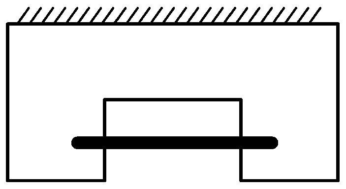
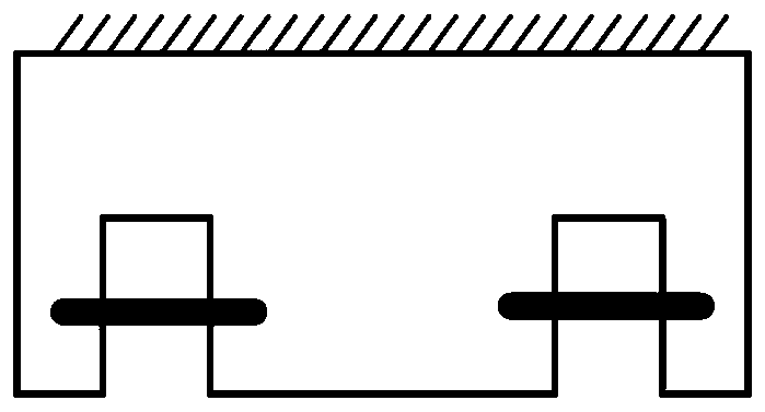
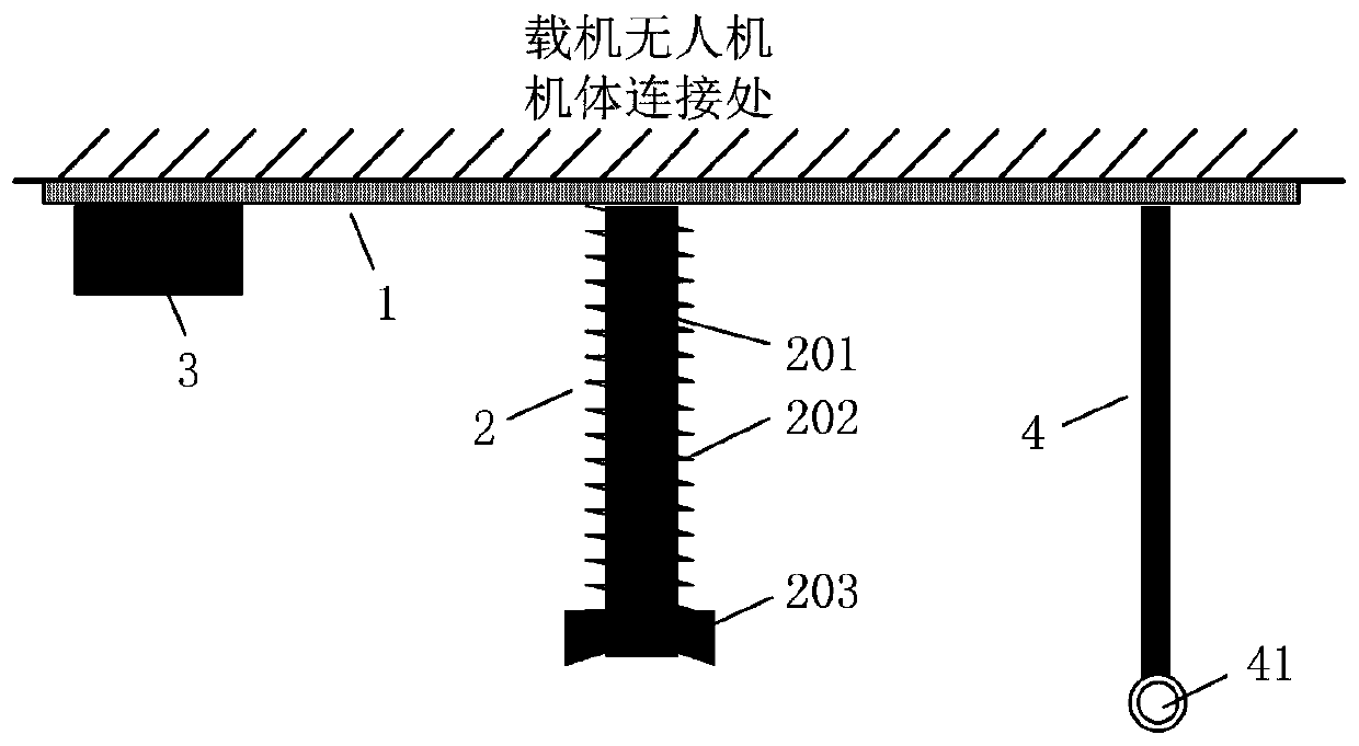
[0042] The mounting, launching and timing control device of the small unpowered unmanned aerial vehicle of the present invention is composed of multiple sets of mechanical loading brackets and a timing control circuit for controlling the launching of the multiple sets of mechanical loading brackets.

[0043] (1) Mechanical loading bracket

[0044] Such as figure 2 As shown, the mechanical loading bracket includes a base 1 , a loading carbon rod 2 , a steering ge...


PUM


Abstract

The invention provides a small unpowered unmanned aerial vehicle mounting device. The small unpowered unmanned aerial vehicle mounting device comprises a base, a loading carbon rod, a steering engineplug and a rubber bandage, wherein the upper end of the loading carbon rod is fixed in the middle of the base, a spring is arranged in a sleeve mode outside a carbon fiber cylindrical rod, the upper end of the spring is fixed onto the base, the lower end of the spring is fixedly provided with a limiting and fixing device which is internally provided with hole allowing the carbon fiber cylindricalrod to penetrate through, the lower surface of the limiting and fixing device is provided with a groove matched in shape with the surface of an unmanned aerial vehicle to be mounted, one end of the rubber bandage is fixed onto the base and on one side of the loading carbon rod, and the other end of the rubber bandage is a free end; the steering engine plug is fixed onto the base and on the other side of the loading carbon rod for fixing or releasing the free end of the rubber bandage. By means of high-strength and low-weight materials and a relatively simple mounting structure, the small unpowered unmanned aerial vehicle mounting device effectively reduces the overall weight and increase the strength; the unmanned aerial vehicle is in a laminated mounting structure, so that the number of mounting can be effectively increased, and the loading size can be reduced.

Description

technical field [0001] The invention relates to the technical field of loading and launching control of aircraft loads, in particular to a small unpowered unmanned aerial vehicle mounting device. Background technique [0002] As we all know, UAV is an unmanned aircraft that can perform tasks autonomously only through radio remote control instructions and program control. It has many advantages such as high flexibility, low cost, and convenient use. It is widely used in civilian and military applications. and other fields. [0003] There are many ways for drones to take off, such as rocket launch, runway roll, and high-altitude drop. It can perform a variety of tasks, such as high-altitude target drones, military reconnaissance, and target strikes. For traditional mounting tasks, commonly used hanger forms are shown in Figure 1(a) and Figure 1(b), where Figure 1(a) is a single-point hanger and Figure 1(b) is a multi-point hanger shelf. Usually, the upper part of the pylon...

Claims


Application Information

Patent Timeline
Patent Type & Authority Applications(China)
IPC IPC(8): B64D9/00B64D5/00B64D1/02B64D47/00
CPCY02T50/40
Inventor 王恺郭建新褚鹏霍文俊朱锐陈雅蓉
Owner XIJING UNIV
Why Eureka
Try Eureka