
Filter brick for biological aerated filter and biological aerated filter adopting filter brick

An aerated biological filter and filter brick technology, which is applied in water aeration, sustainable biological treatment, chemical instruments and methods, etc. problems, to achieve the effect of expanding the scope of use and overcoming the water and air distribution system

Active Publication Date: 2019-05-24
CSD BEIJING E P DEV CO LTD
View PDF5 Cites 6 Cited by
  • Summary
  • Abstract
  • Description
  • Claims
  • Application Information

AI Technical Summary

Problems solved by technology

The following problems will arise during the construction and operation of the system: civil engineering and installation are complicated, the construction period is long, and the construction accuracy is not easy to guarantee; a 1-meter-high filter chamber needs to be installed below the filter plate for the installation of air distribution pipelines and daily maintenance. The filter chamber occupies a large volume of the pool but does not play a role in removing pollutants, which is a waste volume
Since the biological aerated filter needs continuous aeration during operation, the current filter bricks cannot achieve good aeration and at the same time achieve downward flow of water filtration

Method used


Image

  • Filter brick for biological aerated filter and biological aerated filter adopting filter brick
  • Filter brick for biological aerated filter and biological aerated filter adopting filter brick
  • Filter brick for biological aerated filter and biological aerated filter adopting filter brick

Examples


Embodiment Construction

[0023] The objects and functions of the present invention and methods for achieving the objects and functions will be clarified by referring to the exemplary embodiments. However, the present invention is not limited to the exemplary embodiments disclosed below; it can be implemented in various forms. The essence of the description is only to help those skilled in the relevant art comprehensively understand the specific details of the present invention.

[0024] Hereinafter, embodiments of the present invention will be described with reference to the accompanying drawings. In the drawings, the same reference numerals represent the same or similar components, or the same or similar steps.

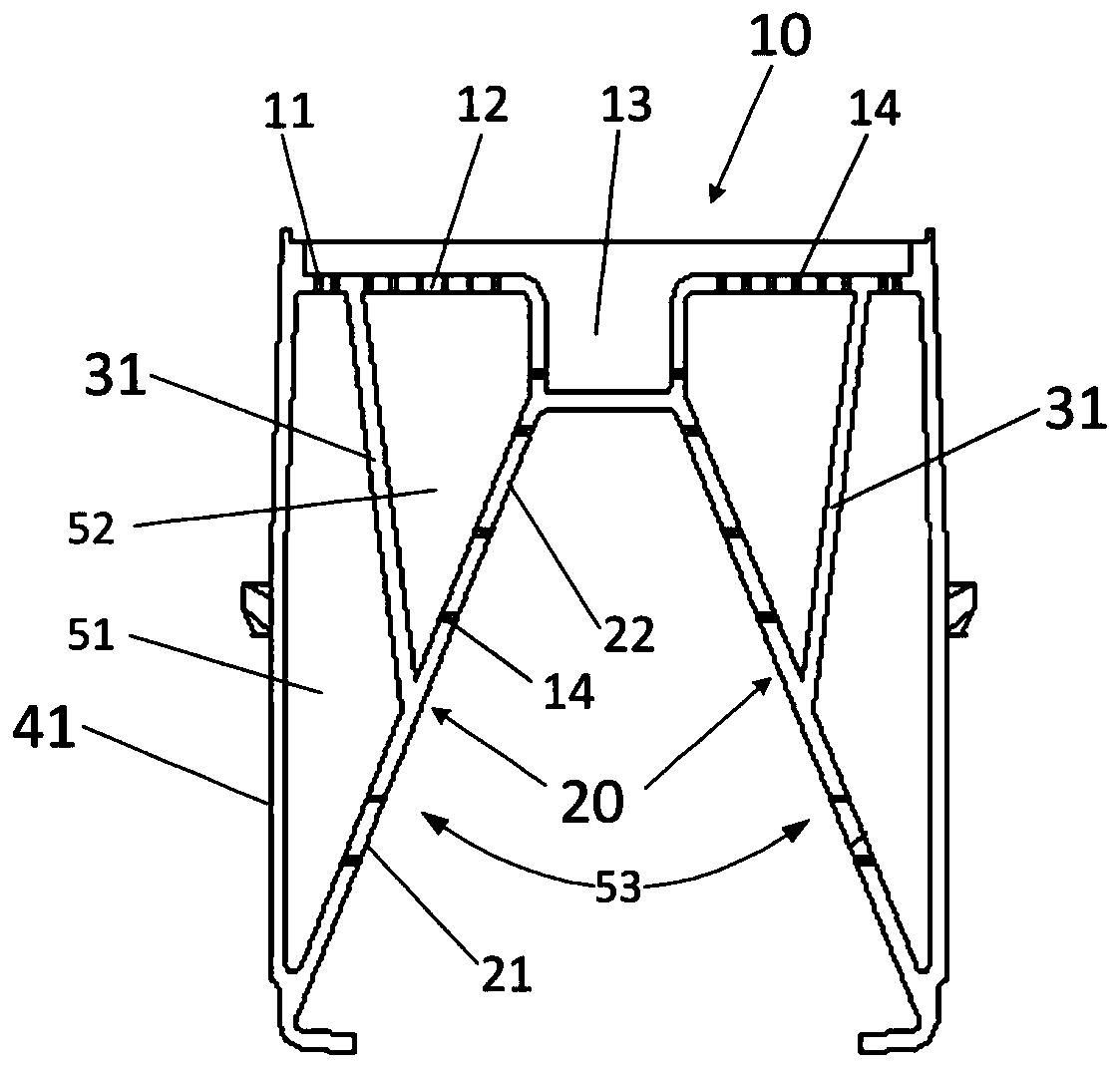
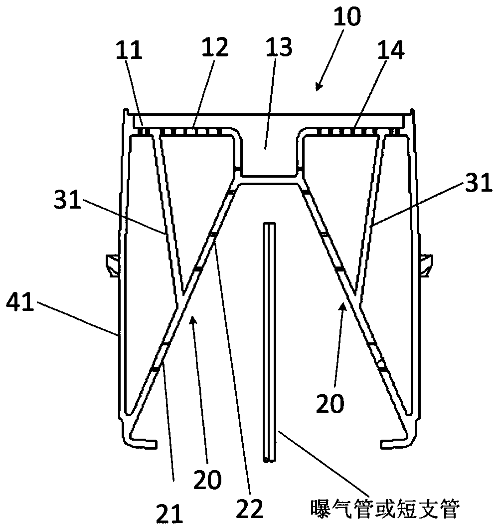
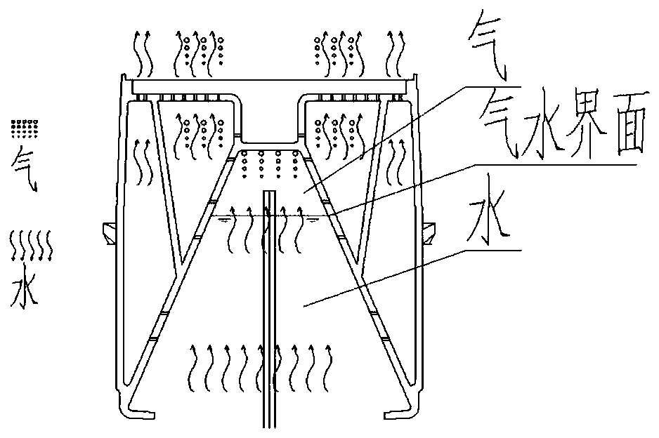
[0025] as attached Figure 1 to Figure 2 As shown, schematically shows a vertical cross-sectional view of an embodiment of a filter brick for a biological aerated filter according to the present disclosure.

[0026] In the illustrated filter brick for a biological aerated filter, there is...


PUM


Abstract

The invention provides a filter brick for a biological aerated filter. The filter brick comprises a first chamber extending from the bottom to the top of the filter brick, wherein the cross sectionalarea of the first chamber is gradually reduced from bottom to top; a pore plate provided with a plurality of pores is arranged on the first chamber laterally, a partition plate is arranged on the filter brick and positioned between the middle position and the top wall of the pore plate, the pore plate is divided into an upper pore plate portion and a lower pore plate portion at the junction of thepore plate and the partition plate, and the top wall is divided into a first top wall portion and a second top wall portion at the junction of the top wall and the partition plate; the lower pore plate part, the side wall of the filter brick, the first top wall portion and the partition plate form a second chamber, the first top wall portion is provided with holes, and the first top wall portionis adjacent to the side wall; and the upper pore plate portion, the second top wall portion and the partition plate form a third chamber, the second top wall portion is provided with holes, and the partition plate separates the second chamber from the third chamber. The invention also provides a biological aerated filter adopting the filter brick.

Description

technical field [0001] The invention relates to the field of sewage treatment, in particular to a filter brick used for an aerated biological filter and an aerated biological filter using the filter brick. Background technique [0002] Biological aerated filter, referred to as BAF ((Biological Aerated Filter), is a new type of biofilm sewage treatment process developed in Europe and the United States in the late 1980s. It was greatly developed in the early 1990s, with a maximum scale of hundreds of thousands of tons. Every day, and developed to be able to remove nitrogen and phosphorus. This process has the functions of removing SS (suspended solids), COD (chemical oxygen demand), BOD (biochemical oxygen demand), nitrification, denitrification, phosphorus removal, removal of AOX (hazardous substances ), the biological aerated filter is a new process that integrates biological oxidation and interception of suspended solids. [0003] The biological aerated filter in the prior...

Claims


Application Information

Patent Timeline
IPC IPC(8): C02F3/02C02F7/00
CPCY02W10/10
Inventor 蔡文孙召强祁淑敏王忠民张阳王佳君卫朋飞
Owner CSD BEIJING E P DEV CO LTD
Learn More