Housing suspended ceiling structure

A technology for roof panels and suspended ceilings, applied to ceilings, building components, building structures, etc., can solve problems such as looseness, difficult adjustment, and large friction, and achieve the effect of reducing resistance

Active Publication Date: 2019-05-24
WENZHOU SHENBANG MUNICIPAL ENG CO LTD
View PDF3 Cites 4 Cited by
  • Summary
  • Abstract
  • Description
  • Claims
  • Application Information

AI Technical Summary

Problems solved by technology

But square plate 6 is installed one by one in the process of installation, needs to install two clamping boards 61 in a bayonet socket 51, does not isolate each other between two clipping boards 61, when snapping in the bayonet socket 51 the second When a clamping plate 61 is formed, the first clamping plate 61 may become loose relative to the bayonet socket 51; and after the second clamping plate 61 is inserted into the bayonet socket 51, the position of the second square plate 6 still needs to be adjusted. The second clamping plate 61 will slide relative to the first clamping plate 61, and under the clamping effect of the bayonet 51 of the triangular keel 5, the frictional force between the two clamping plates 61 is relatively large , it is relatively difficult to adjust

Method used


Image

  • Housing suspended ceiling structure
  • Housing suspended ceiling structure
  • Housing suspended ceiling structure

Examples


Embodiment Construction

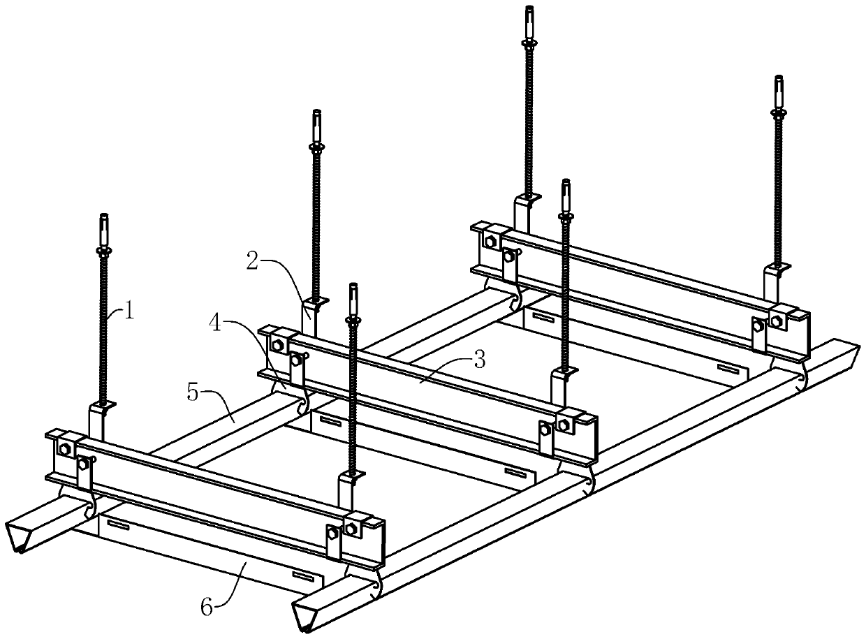
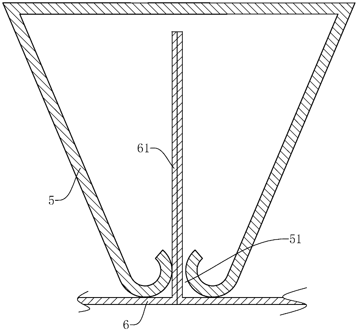
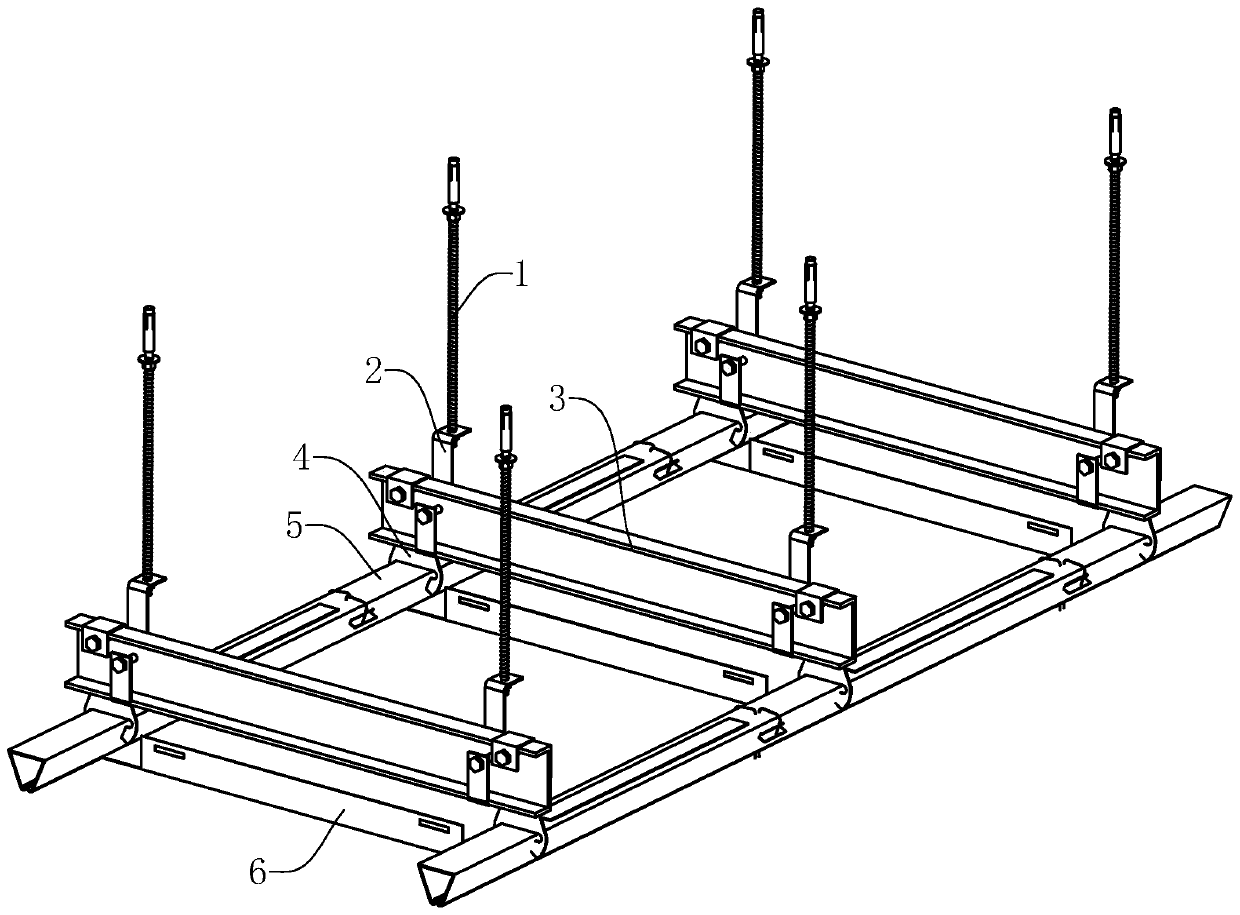
[0035] Such as image 3 As shown, the present invention introduces a suspended ceiling structure of a house, which includes a suspender 1, a main keel 3, a triangular keel 5 and a square plate 6. set horizontally and in parallel between the triangular keels 5, and the triangular keels 5 and the main keel 3 are perpendicular to each other, the main keel 3 is hoisted under the boom 1, and the triangular keels 5 are fixed on the bottom of the main keel 3 Below, the square plate 6 is clamped and fixed below the triangular keel 5 .

[0036] In this example, if image 3 As shown, the main keel 3 is connected to the boom 1 through the main hanger 2 , and the triangular keel 5 is connected to the main keel 3 through the triangular hanger 4 . The structure of the main hanger 2 can refer to the "connector" in the invention patent with the publication number CN105386556A, and the structure of the triangle hanger 4 can refer to the "triangle hanger" in the invention patent with the auth...


PUM


Abstract

The invention relates to the field of indoor decoration, in particular to a housing suspended ceiling structure, comprising suspending rods, main keels, triangular keels and square plates. Each triangular keel comprises a main sheet and partitions, the main sheet is bent into a main structure with triangular section, the bent sides of the main sheet are close to each other and form a clamping opening, the partitions are positioned in the main sheet and are perpendicular to a bottom plate facing the clamping opening, the end of each partition close to the clamping opening is positioned in the clamping opening, and the partitions divide the clamping opening into a first clamping opening and a second clamping opening. Upon mounting of the square plates, clamp plates clamped to the two squareplates inside each triangular keel are clamped in respectively from the first and second clamping openings, so that the clamp plates of the two square plates can be separated by the partitions and dotnot interfere each other. Therefore, during mounting and adjusting of one square plate, the position of the other square plate is never affected.

Description

technical field [0001] The invention relates to the field of interior decoration, in particular to a suspended ceiling structure of a house. Background technique [0002] In interior decoration, the suspended ceiling of a house is a very important decoration project. The suspended ceiling has the functions of heat preservation, heat insulation, sound insulation and sound absorption. The integrated ceiling is a very commonly used ceiling structure in the ceiling. It is easy to install, flexible in layout, and easy to maintain. It has gradually become the mainstream of bathroom and kitchen ceilings. [0003] Such as figure 1 As shown, the existing integrated suspended ceiling includes a boom 1, a main hanger 2, a main keel 3, a triangle hanger 4, a triangle keel 5 and a square plate 6, and the hanger 1 is vertically suspended under the roof of the house through expansion bolts , the main hanger 2 is connected under the boom 1, the main keel 3 is connected to the bottom of th...

Claims


Application Information

Patent Timeline
IPC IPC(8): E04B9/00E04B9/06E04B9/18
Inventor 高乐秀陈兆林黄云福诸云芹诸葛森豪
Owner WENZHOU SHENBANG MUNICIPAL ENG CO LTD
Why Eureka
Try Eureka