Automatic insertion type vibrating device for tunnel secondary lining concrete

A technology of automatic insertion and vibrating device, applied in the direction of tunnel lining, tunnel, shaft lining, etc., can solve the problems of void of the second lining of the vault, artificial inability to vibrate the concrete, and the concrete is not compacted, so as to reduce the amount of grouting with molds. , The effect of reducing labor intensity and safety risks, and improving construction efficiency and quality

Pending Publication Date: 2019-05-24
NO 4 ENG CO LTD OF CHINA RAILWAY 11 BUREAU GRP +1
View PDF0 Cites 2 Cited by
  • Summary
  • Abstract
  • Description
  • Claims
  • Application Information

AI Technical Summary

Problems solved by technology

[0004] The purpose of the present invention is to solve the major safety risks such as the second lining vault concrete of the existing tunnel cannot be manually vibrated, relying entirely on the natural topping method of the concrete delivery pump, which easily leads to the void of the second lining of the vault and the concrete is not dense, etc., to provide a tunnel Automatic plug-in vibrating device for second-lined concrete

Method used


Image

  • Automatic insertion type vibrating device for tunnel secondary lining concrete
  • Automatic insertion type vibrating device for tunnel secondary lining concrete
  • Automatic insertion type vibrating device for tunnel secondary lining concrete

Examples


Embodiment Construction

[0018] The present invention will be further described in detail below in conjunction with the accompanying drawings and specific embodiments.

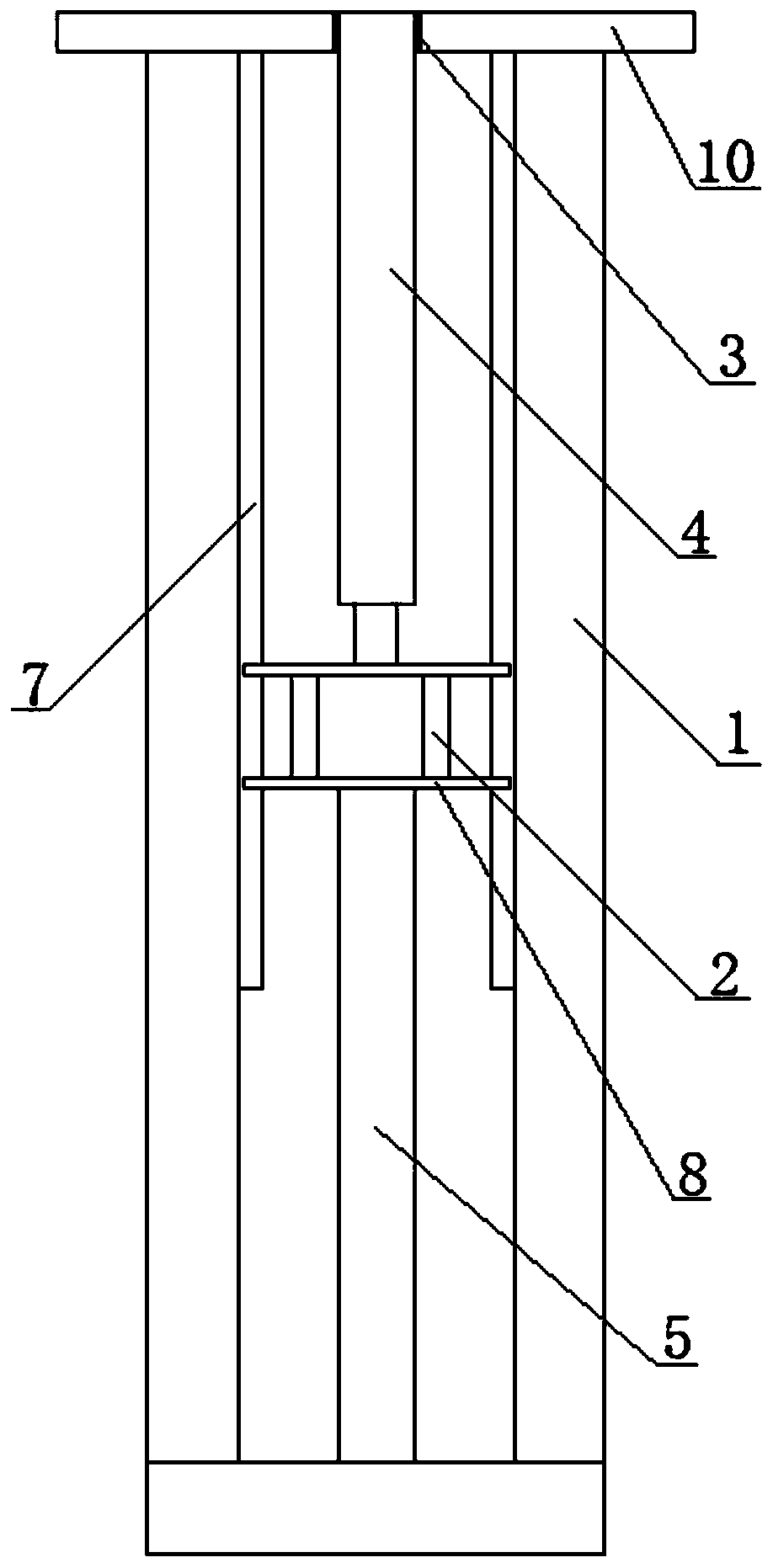
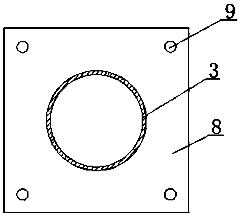
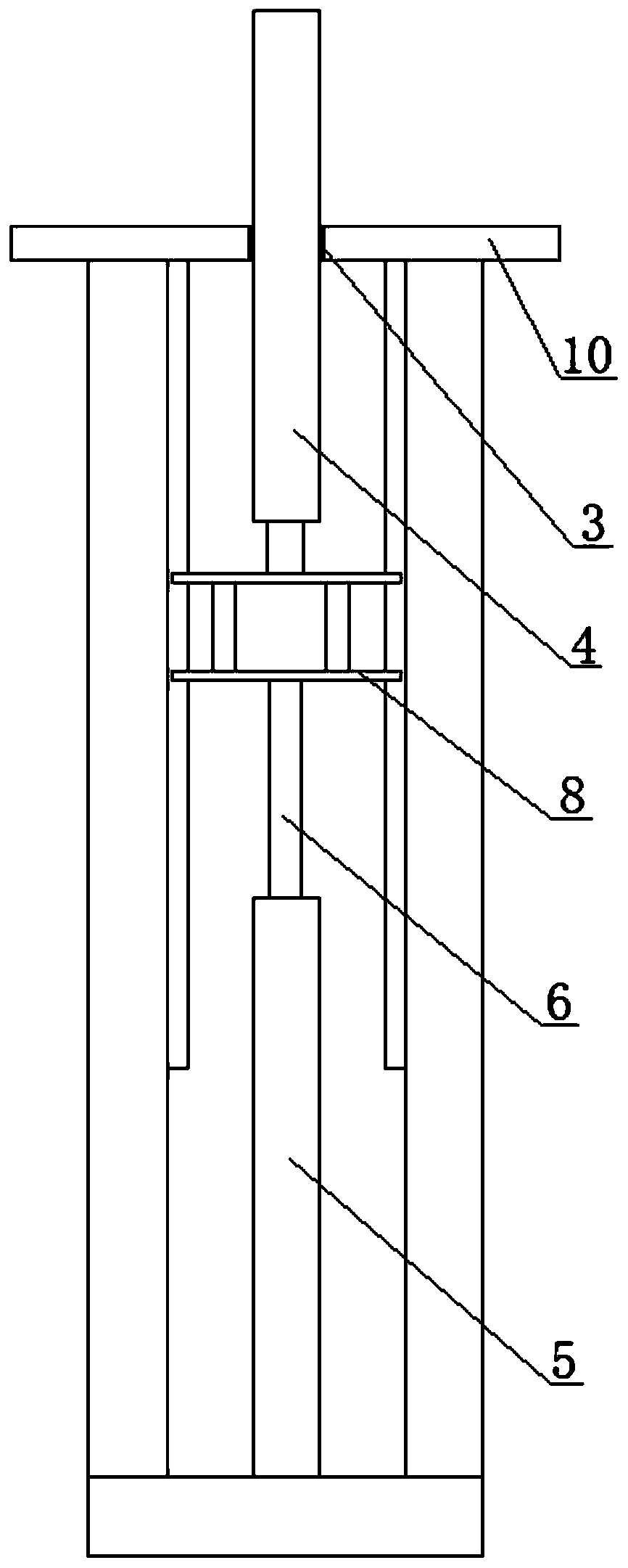
[0019] see Figure 1 to Figure 3 , an automatic plug-in vibrating device for second lining concrete of a tunnel, relates to automatic concrete vibrating during tunnel lining construction, including a steel frame 1, a pneumatic jacking device 5, a jacking slideway 7, a high frequency vibrating rod 4, and a gas compression machine and electric control box.

[0020] see Figure 1 to Figure 3 , the steel frame 1 is installed on the back side of the steel formwork 10 of the second lining trolley of the tunnel, that is, the steel frame 1 is installed on the surface of the steel formwork 10 of the second lining trolley of the tunnel facing the inside of the trolley, and the steel frame 1 is installed Closely attached to the back of the steel formwork 10 of the second lining trolley. The pneumatic jack 5 is installed at the center of the b...


PUM


Abstract

The invention relates to an automatic insertion type vibrating device for tunnel secondary lining concrete. The automatic insertion type vibrating device comprises a steel frame (1), a pneumatic jacking device (5), a jacking slideway (7), a high-frequency vibrating rod (4), a gas compressor and an electric control cabinet and is characterized in that the steel frame (1) is mounted on the back of atunnel secondary lining trolley steel form board (10), the pneumatic jacking device (5) is mounted at the bottom of the steel frame (1), the jacking slideway (7) comprises a slideway steel plate andmounting slide grooves arranged in two inner sides of the steel frame (1), the pneumatic jacking device (5) is connected with the gas compressor, the top of the jacking air cylinder column (6) of thepneumatic jacking device (5) is connected with the slideway steel plate (8), the bottom of the high-frequency vibrating rod (4) is fixed onto the slideway steel plate (8), the upper portion of the high-frequency vibrating rod (4) is inserted into the secondary lining trolley steel form board (10), and the top of the high-frequency vibrating rod (4) is parallel with the surface of the secondary lining trolley steel form board (10). By the automatic insertion type vibrating device, automatic insertion type vibrating of the tunnel secondary lining concrete is achieved.

Description

technical field [0001] The invention relates to a concrete vibrating device, in particular to an automatic insertion type vibrating device for second lining concrete of a tunnel, which belongs to the technical field of tunnel lining construction. Background technique [0002] At present, with the rapid development of high-speed rail in my country, there are more and more tunnels; with the continuous improvement of tunnel lining quality and standardized construction requirements, the quality requirements of tunnel lining concrete are getting higher and higher. [0003] In the traditional tunnel lining process, the tunnel second lining trolley is positioned and then the delivery pump pipe is reinforced and installed. The ready-mixed concrete is sent to each sub-window of the second lining trolley through the concrete drag pump, and each sub-window is poured. Use a hand-held vibrator to vibrate while pouring, and use natural pump pressure to punch the top when pouring the vault...

Claims


Application Information

Patent Timeline
Patent Type & Authority Applications(China)
IPC IPC(8): E21D11/10E04G21/08
Inventor 操光伟黎庶李俊王更峰李行利朱向阳焦贤福
Owner NO 4 ENG CO LTD OF CHINA RAILWAY 11 BUREAU GRP
Why Eureka
Try Eureka