Vault concrete pouring early warning device and construction method thereof
A technology of concrete and early warning, which is applied in the direction of earthwork drilling, shaft equipment, shaft lining, etc. It can solve the problems of vault falling, affecting operation safety, high processing and maintenance costs, etc., and achieves the reduction of grouting costs and the lining structure. Good integrity, the effect of lining structure integrity control
- Summary
- Abstract
- Description
- Claims
- Application Information
AI Technical Summary
Problems solved by technology
Method used
Image
Examples
Embodiment 1
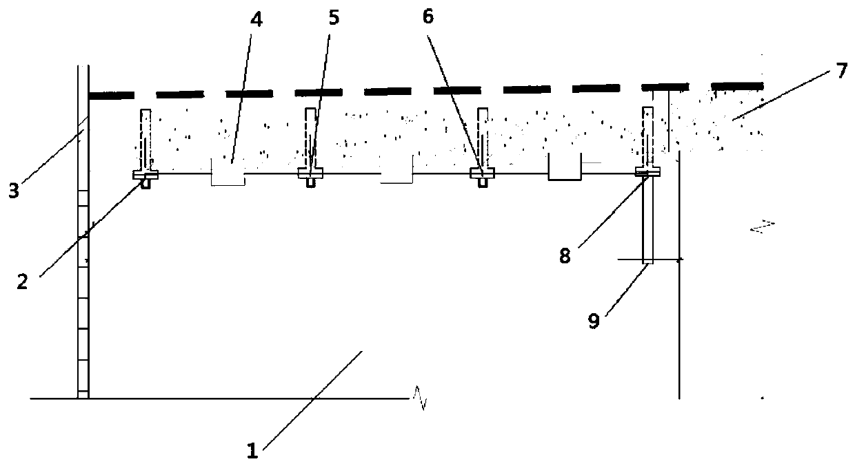
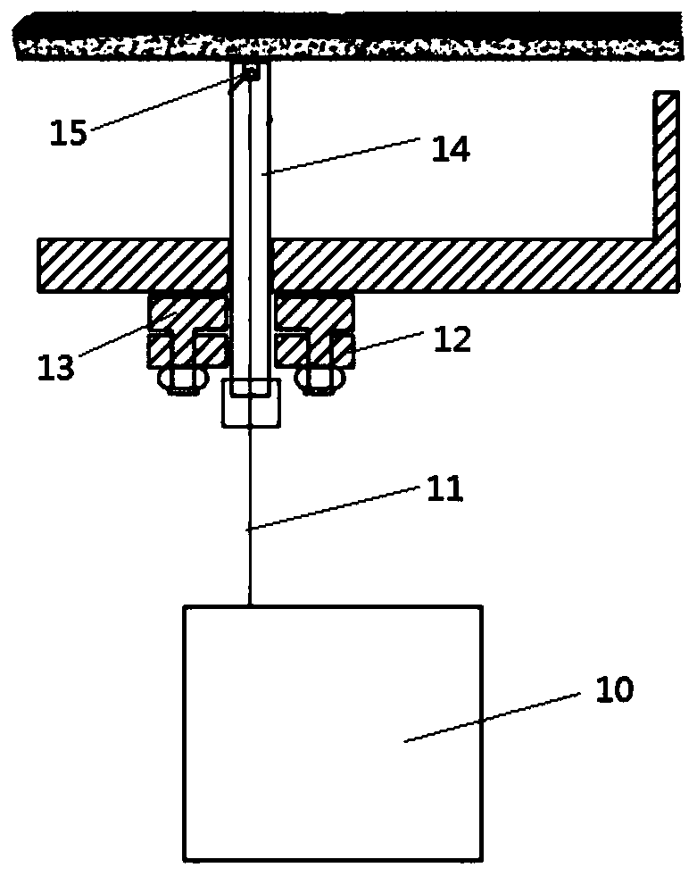
[0031] see Figure 1~2 , in an embodiment of the present invention, a vault concrete pouring early warning device includes a secondary lining trolley 1, the front end of the secondary lining trolley 1 is provided with a trolley end mold 3, and the arch of the secondary lining trolley 1 There are four grouting holes along the longitudinal direction of the trolley at the center line of the top. The four grouting holes are No. 4 grouting hole 2 for end mold exhaust and No. 3 grouting hole for middle exhaust. The grouting hole 5, the No. 2 grouting hole 6 and the No. 1 grouting hole 8 used to communicate with the pre-embedded grouting pipe 14, the distance between the No. 4 grouting hole 2 and the trolley end mold 3 is 0.6-0.8m , the distance between No. 1 grouting hole 8 and trolley end mold 3 is 1-1.2m, No. 2 grouting hole 6 and No. 3 grouting hole 5 are evenly distributed in No. 4 grouting hole 2 and No. 1 grouting hole Between the holes 8; the bottom of the embedded grouting ...
Embodiment 2
[0035] see Figure 1~2 , a construction method of a vault concrete perfusion early warning device, is characterized in that, comprising the following steps:
[0036] (1) Four grouting holes are opened along the longitudinal direction of the trolley at the center line of the vault of the secondary lining trolley 1, and the four grouting holes are No. Grouting hole 2, No. 3 grouting hole 5 and No. 2 grouting hole 6 for intermediate exhaust, and No. 1 grouting hole 8 for connecting to embedded grouting pipe 14, No. 4 grouting hole 2 and trolley The distance between the end molds 3 is 0.6-0.8m, and the distance between the No. 1 grouting hole 8 and the trolley end mold 3 is 1-1.2m;
[0037] (2) Weld the fixed flange 13 and the positioning flange 12 at the opening of the No. 1 grouting hole 8. The fixed flange 13 and the positioning flange 12 are fixedly connected by full welding, and then the four probes are fixedly installed on the On the overflow tank on the pre-embedded grout...
PUM
 Abstract
Description
Claims
Application Information
 - R&D
- Intellectual Property
- Life Sciences
- Materials
- Tech Scout
- Unparalleled Data Quality
- Higher Quality Content
- 60% Fewer Hallucinations
Browse by: Latest US Patents, China's latest patents, Technical Efficacy Thesaurus, Application Domain, Technology Topic, Popular Technical Reports.
© 2025 PatSnap. All rights reserved.Legal|Privacy policy|Modern Slavery Act Transparency Statement|Sitemap|About US| Contact US: help@patsnap.com


