
Ferromagnetic pipeline stress detection and monitoring method

A technology of stress detection and pipeline, which is applied in the detection field, can solve the problems of reduced missed detection rate and inability to accurately locate pipelines, and achieve the effects of reduced missed detection rate, safe and risk-free operation, and easy on-site implementation

Pending Publication Date: 2019-05-24
CHENGDU QIBO NEW ENERGY RES INST +1
View PDF5 Cites 8 Cited by
  • Summary
  • Abstract
  • Description
  • Claims
  • Application Information

AI Technical Summary

Problems solved by technology

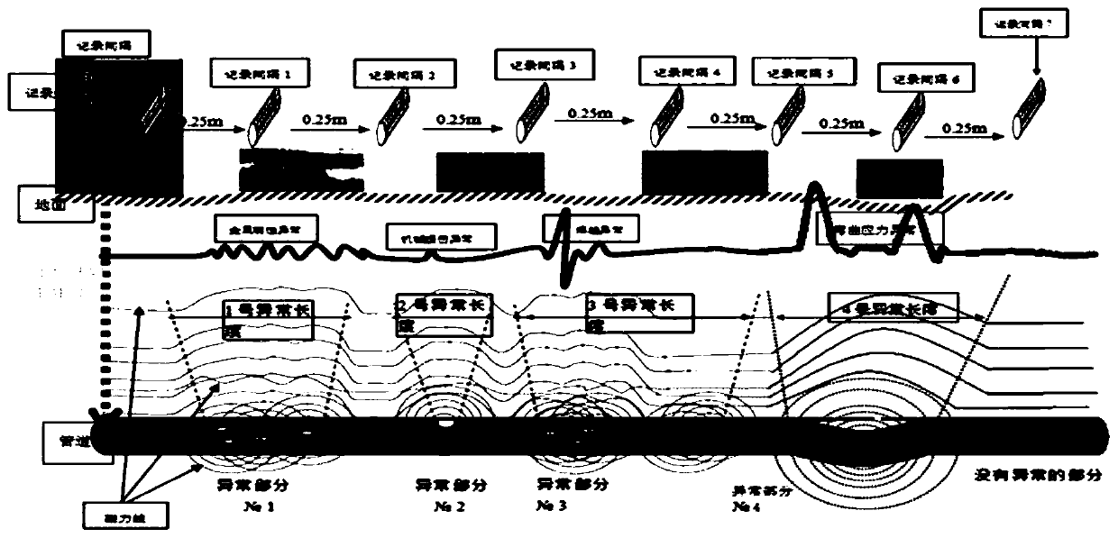
[0005] The purpose of the present invention is to provide a ferromagnetic pipeline stress detection and monitoring method, which overcomes various drawbacks in the existing ferromagnetic pipeline stress detection and monitoring methods, such as the inability to accurately locate the stress concentration point of the pipeline and its stress value; The magnetic field uniformly magnetizes the ferromagnetic pipeline, combined with the characteristics of the magnetic field signal when the ferromagnetic pipeline is under stress, it can accurately find the stress concentration point of the pipeline, which greatly simplifies the detection process; at the same time, the missed detection rate is greatly reduced, and the operation is safe and risk-free , easy to implement on-site

Method used


Image

  • Ferromagnetic pipeline stress detection and monitoring method
  • Ferromagnetic pipeline stress detection and monitoring method
  • Ferromagnetic pipeline stress detection and monitoring method

Examples


Embodiment Construction

[0029] A ferromagnetic pipeline stress detection and monitoring method of the present invention comprises the following steps:

[0030] (1) Determine the basic information of the pipeline

[0031] Check and analyze the pipeline design, pipeline operation and operation documents in the area to be tested, and make a preliminary judgment on the possible stress concentration of the pipeline according to the characteristics of the pipeline.

[0032] (2) Determine the pipeline routing and buried depth

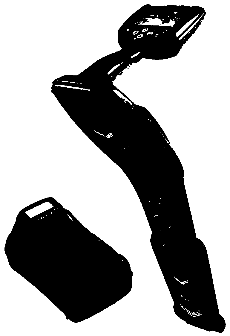
[0033] Visually inspect the path of the pipeline to be tested, clean up the debris on both sides of the pipeline axis, and record the terrain and buildings around the pipeline to facilitate the detection and calibration of the subsequent pipeline path; use the Radiodetection 8000 underground pipeline detector to detect the pipeline path, Then use the Global Positioning System (GPS) to determine the position of the path control point or temporary reference mark, and detect the zero p...


PUM


Abstract

The invention relates to a ferromagnetic pipeline stress detection and monitoring method. The method includes the steps of firstly, collecting pipeline basic information, and primarily judging parts where stress concentration possibly occurs; secondly, determining a pipeline route and buried depth, to be more specific, visually measuring the pipeline route, cleaning sundries, using a pipe locatorto detect the route, setting positioning piles, and measuring pipeline buried depth at the same time; thirdly, using a noncontact scanning magnetometer to collect magnetic signals along the calibratedroute; fourthly, analyzing and processing data, to be more specific, determining the axial position and circumferential position of the stress concentration parts of the pipeline; fifthly, detectingand monitoring pipeline stress, to be more specific, circumferentially adhering resistance strain gauges to the surfaces of the stress concentration points of the pipeline, and determining the stressvalue of the stress concentration points according to stress-strain relation; using the general packet radio service technology to transmit data to achieve remote data transmission and control. By themethod, the defects that existing ferromagnetic pipeline stress detection cannot accurately position the pipeline stress concentration points and determine the stress value of the stress concentration points are overcome, and omission factor is lowered greatly.

Description

technical field [0001] The invention belongs to the field of detection methods, and in particular relates to a stress detection and monitoring method for oil and gas buried ferromagnetic pipelines. Background technique [0002] The damage of the material under the action of alternating stress is called fatigue damage. Usually, when the alternating stress of the material is much smaller than its strength limit under the static load, the damage may occur. In addition, the material will cause local stress due to the change of the cross-sectional size. This phenomenon is called stress concentration. For oil and gas buried ferromagnetic pipelines, the stress concentration is easy to change the mechanical properties, which will eventually lead to the decrease of corrosion resistance, the increase of fatigue strength, and the decrease of fatigue life, etc., which are often difficult to be found, so there is an urgent need for a The method can accurately locate the stress concentra...

Claims


Application Information

Patent Timeline
Patent Type & Authority Applications(China)
IPC IPC(8): G01N27/83G01L5/00
Inventor 汪鹏飞徐震张明李安军邢占员王鲜刘艳军
Owner CHENGDU QIBO NEW ENERGY RES INST
Learn More