

Hot rolled alloy steel flaw detection device
A flaw detection device, alloy steel technology, applied in measuring devices, using sound waves/ultrasonic waves/infrasonic waves to analyze solids, using sound waves/ultrasonic waves/infrasonic waves for material analysis, etc., to achieve the effect of fast air flow
- Summary
- Abstract
- Description
- Claims
- Application Information
AI Technical Summary
Problems solved by technology
Method used
Image

Examples
Embodiment Construction
[0023] The following will clearly and completely describe the technical solutions in the embodiments of the present invention with reference to the accompanying drawings in the embodiments of the present invention. Obviously, the described embodiments are only some, not all, embodiments of the present invention.
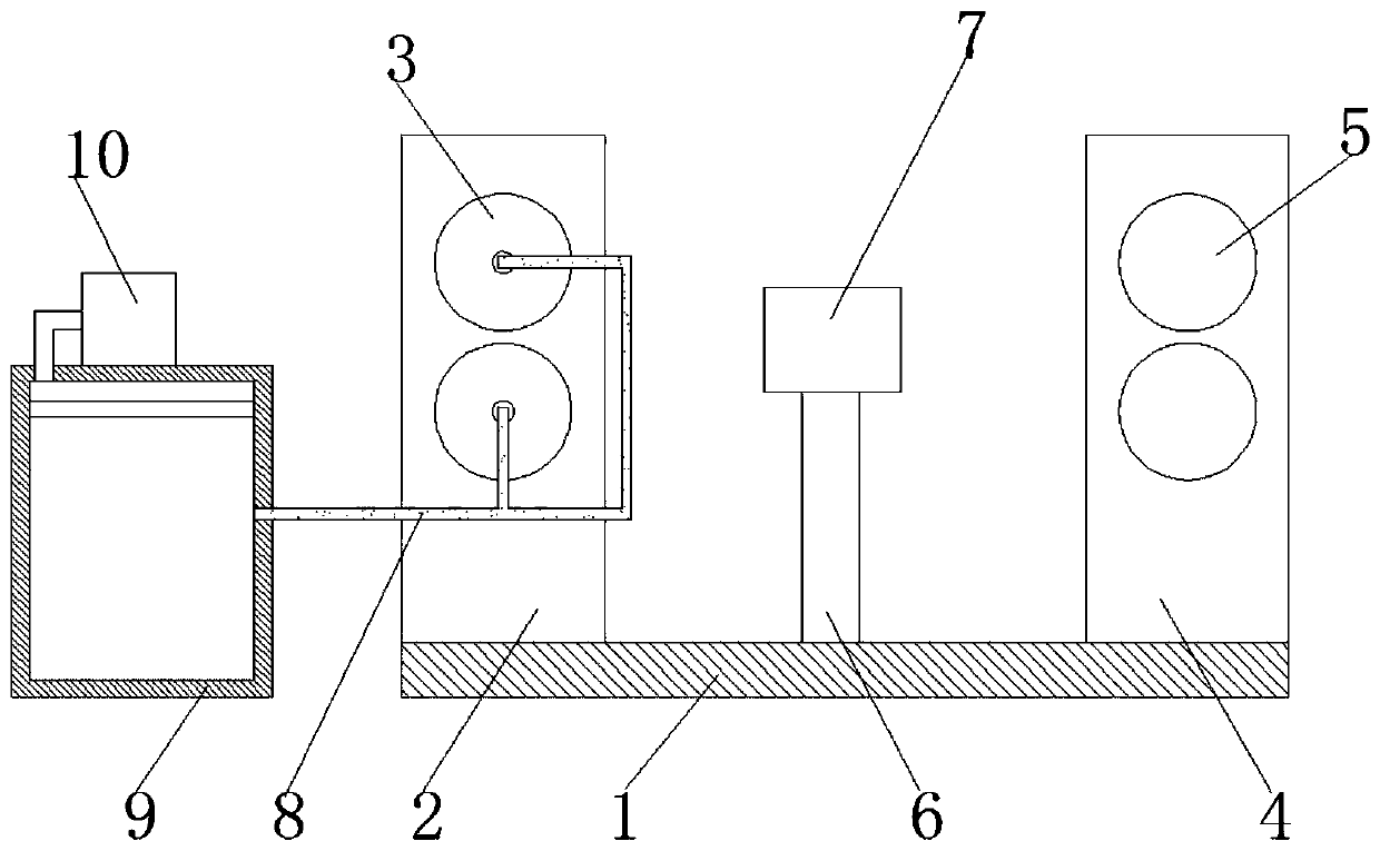
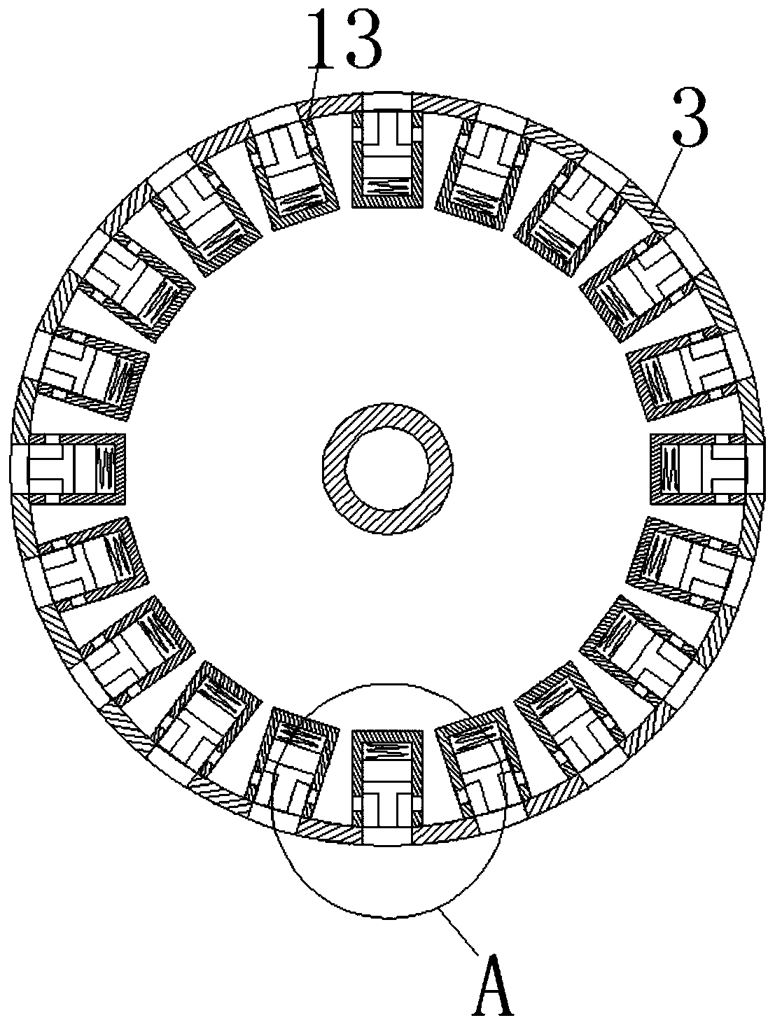
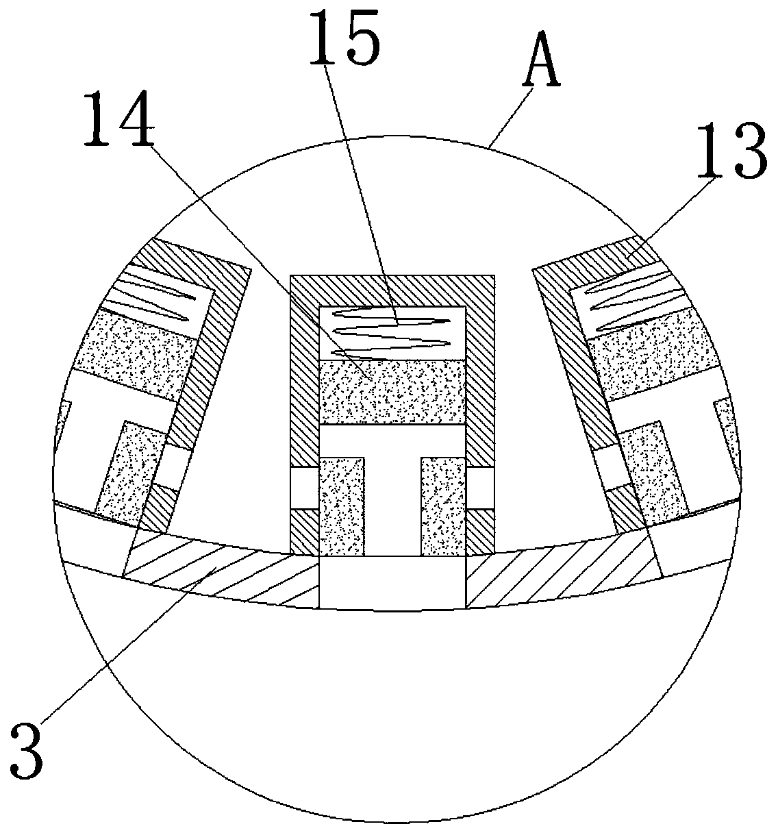
[0024] refer to Figure 1-6 , a flaw detection device for hot-rolled alloy steel, including a base 1 and an ultrasonic flaw detector 7, the upper end of the base 1 is provided with a first support plate 2, a second support plate 4 and a support rod 6, and the first support plate 2 and The second support plate 4 is on the same plane, and the support rod 6 is located between the first support plate 2 and the second support plate 4, and the first drive plate 3 is arranged on the first support plate 2, The number of the first driving disc 3 is two, and there is a gap between the first driving discs 3, the first driving disc 3 is installed on the first support plate 2 thr...
PUM
 Abstract
Description
Claims
Application Information