S-shaped turbulent flow structure for large-air-volume surfacing type plate heat exchanger

A technology of plate heat exchanger and large air volume, which is applied in the direction of heat exchanger shell, heat exchange equipment, lighting and heating equipment, etc. Large heat exchange area and the effect of improving heat exchange efficiency

Inactive Publication Date: 2021-07-13
XI AN JIAOTONG UNIV
View PDF8 Cites 0 Cited by
  • Summary
  • Abstract
  • Description
  • Claims
  • Application Information

AI Technical Summary

Problems solved by technology

[0002] Plate heat exchangers are widely used due to their advantages of high overall heat transfer coefficient, low refrigerant storage and high compactness. Among them, corrugated plate heat exchangers are the most commonly used plate heat exchangers in recent years, but corrugated plate heat exchangers The thickness of the heater plate is relatively thin, and after being pressed into corrugations, the plate wall is even thinner, and under the condition of large air volume, the plate that is too thin is prone to airflow turbulence, and the bearing capacity is low. The heat plate is damaged, which greatly reduces the heat transfer efficiency
[0003] The pressed corrugated plate heat exchanger has disadvantages such as low heat exchange efficiency, high flow resistance, insufficient strength, easy scaling and difficult cleaning, especially the corrugated plate heat exchanger begins to scale after a few months of actual operation, making the pressure The drop increases, the load drops rapidly, and the corrosion under the scaling occurs earlier than the dew point corrosion, which seriously shortens the life of the equipment

Method used


Image

  • S-shaped turbulent flow structure for large-air-volume surfacing type plate heat exchanger
  • S-shaped turbulent flow structure for large-air-volume surfacing type plate heat exchanger
  • S-shaped turbulent flow structure for large-air-volume surfacing type plate heat exchanger

Examples


Embodiment Construction

[0026] The technical solutions of the present invention will be described in connection with the examples and the drawings, and the description is clearly, and the embodiments described are intended, and the described embodiments are the embodiments of the present invention, not all of the embodiments.

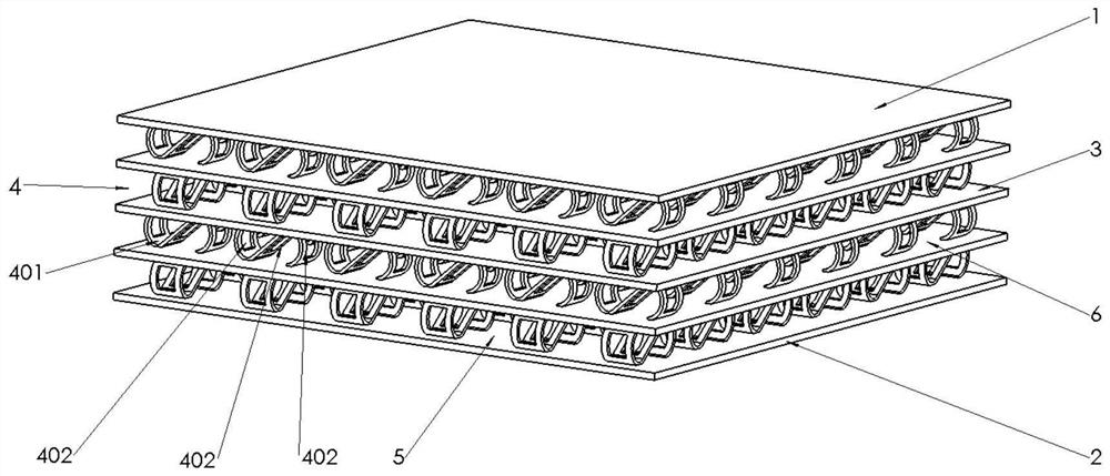
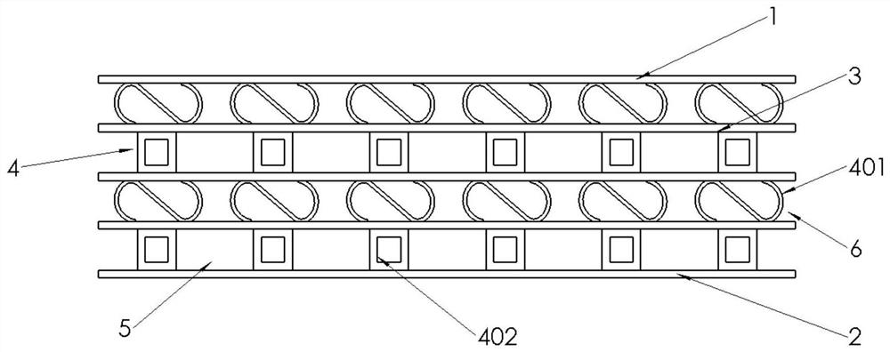
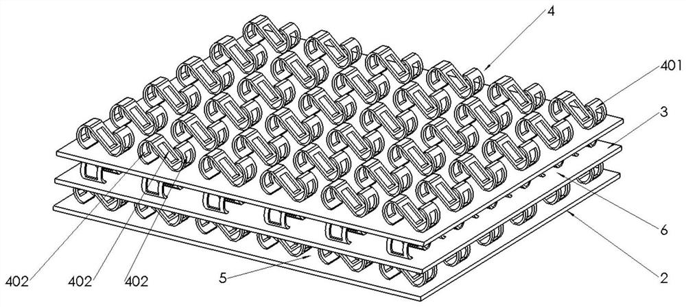
[0027] Refer figure 1 , figure 2 with image 3 A S-shaped spoiler structure for a large wind quantity surfacing plate heat exchanger, including the upper layer plate 1, the lower layer plate 2, and has three medium separator 3 between the upper layer plate 1 and the lower plate 2. Between the upper plate 1 and the middle partition 3, between the adjacent spacers 3, there is a S-type insert 4 between the middle partition plate 3 and the lower layer plate 2, the cooling airflow 5 and the high temperature air flow 6 in the S type In-inventory 4 blended.

[0028] Refer Figure 4 , Figure 5 with Figure 6 The S-shaped insert 4 is arranged by a S-band 401 by a compliant or misalignment, an...


PUM


Abstract

An S-shaped turbulent flow structure for a large-air-volume surfacing type plate heat exchanger comprises an upper-layer plate and a lower-layer plate; two or more middle partition plates are arranged between the upper-layer plate and the lower-layer plate, S-shaped imbedding pieces are arranged between the upper-layer plate and the middle partition plates, between the adjacent middle partition plates and between the middle partition plates and the lower-layer plate, and cooling airflow and high-temperature airflow are mixed in the S-shaped imbedding pieces; the S-shaped imbedding pieces are formed by arranging S belts in sequence or in a staggered mode, the cooling airflow and the high-temperature airflow pass through the S belts of the S-shaped imbedding pieces, and the S belts increase the heat exchange area; three hollow grooves are formed in the S belts, and secondary flow disturbance in main flow is enhanced through the three hollow grooves. The heat exchanger has the advantages of high heat exchange performance, low flow resistance, high strength, less scaling and easiness in cleaning, and can be applied to industries such as chemical industry, petrochemical industry, metallurgical steel, electric power and the like.

Description

Technical field [0001] The invention belongs to the technical field of plate heat exchanger, and more particularly to a S-type spoiler structure for a large wind quantity surfacing plate type heat exchanger. Background technique [0002] The plate heat exchanger is widely used because of the high heat transfer coefficient, the refrigerant stock is low and the compactness is high, and the corrugated sheet heat exchanger is a plate heat exchanger most commonly used in recent years, but the corrugated sheet change The thickness of the heat slicer is thinner, and after being pressed into a ripple, the wall is thinner, and the substantial sheet is easily shaped in the case of high winds, and the load capacity is low, and the equipment is very easy to change. The hot plate is damaged and greatly reduces heat exchange efficiency. [0003] The suppressed corrugated plate heat exchanger has a low heat transfer efficiency, high flow resistance, insufficient intensity, easy to scale, and di...

Claims


Application Information

Patent Timeline
Patent Type & Authority Applications(China)
IPC IPC(8): F28F9/24
CPCF28F9/24
Inventor 徐亮田秋霞高建民席雷李云龙陈航航阮麒成李政轩任迪杨政衡
Owner XI AN JIAOTONG UNIV
Why Eureka
Try Eureka