
Method and device for monitoring optical module laser life

A laser and optical module technology, which is applied in the field of optical communication, can solve the problems of inability to accurately estimate the actual life of the module, and achieve the effects of reducing the probability of communication interruption, accurate judgment, and improving reliability

Active Publication Date: 2021-10-22
HISENSE BROADBAND MULTIMEDIA TECH
View PDF3 Cites 0 Cited by
  • Summary
  • Abstract
  • Description
  • Claims
  • Application Information

AI Technical Summary

Problems solved by technology

[0005] Based on this, in order to solve the technical problem that the actual life of each module cannot be accurately estimated in the related art, the present invention provides a method, device, computer equipment and storage medium for monitoring the life of an optical module laser

Method used


Image

  • Method and device for monitoring optical module laser life
  • Method and device for monitoring optical module laser life
  • Method and device for monitoring optical module laser life

Examples


Embodiment Construction

[0032] In order to make the object, technical solution and advantages of the present invention clearer, the present invention will be further described in detail below in conjunction with the accompanying drawings and embodiments. It should be understood that the specific embodiments described here are only used to explain the present invention, not to limit the present invention.

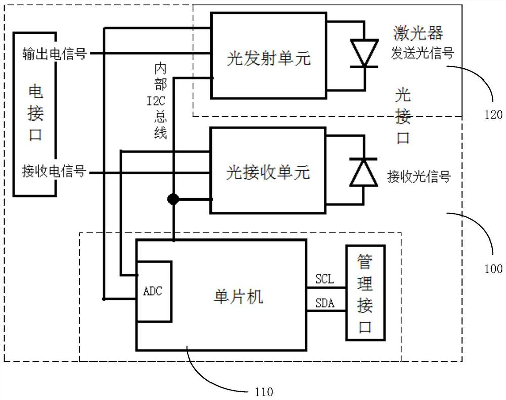
[0033] figure 1 It is an implementation environment diagram of a method for monitoring the life of an optical module laser provided in an embodiment, such as figure 1 As shown, in this implementation environment, an optical module 100 on a telecommunication device is included, and the optical module 100 includes a monitoring module 110 and an optical module laser 120 .

[0034] The telecommunication device is a device interconnected with an external network through an optical fiber, and the optical module 100 is generally used in this device to complete mutual conversion between optical signals an...


PUM


Abstract

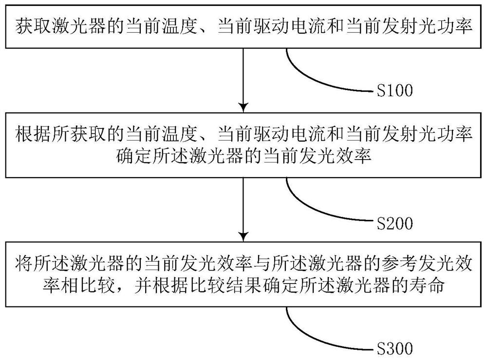
The invention discloses a method and device for monitoring the service life of an optical module laser, belonging to the technical field of optical communication. The method includes: obtaining the current temperature, current driving current and current emission optical power of the optical module laser; , the current driving current and the current emission optical power determine the current luminous efficiency of the optical module laser; compare the current luminous efficiency of the optical module laser with the reference luminous efficiency of the optical module laser, and determine the The lifetime of the optical module laser. This makes the life judgment more accurate, further improves the reliability of life judgment, enables the module to be fully used, and also reduces the probability of communication interruption caused by the short life of the optical module.

Description

technical field [0001] The invention relates to the technical field of optical communication, in particular to a method, a device, a computer device and a storage medium for monitoring the service life of an optical module laser. Background technique [0002] At present, the method of monitoring the life of optical module lasers in the optical module industry is based on the alarm method of the driving current threshold of the optical module laser, while the telecom equipment manufacturers judge based on the current driving current of the optical module laser, but these methods have their limitations. The optical module laser inside the optical module will only generate laser light when the driving current is greater than a certain threshold. The output optical power is different with different driving currents. The temperature has a great influence on the relationship between optical power and driving current. It is difficult to use a driving current to measure the life of ...

Claims


Application Information

Patent Timeline
Patent Type & Authority Patents(China)
IPC IPC(8): H04B10/079
Inventor 林青合王少奇付深圳王安忆李刚
Owner HISENSE BROADBAND MULTIMEDIA TECH
Learn More