Spline groove type flow rate adjusting damping cylinder for intelligent knee joint

A technology of flow regulation and knee joint, which is applied in the field of damping cylinder structure, can solve problems such as failure to reach the designated position, large axial load of the motor, complex structure, etc., and achieve the effects of avoiding damping adjustment failure, continuous damping adjustment, and small mechanism volume

Active Publication Date: 2019-05-28
UNIV OF SHANGHAI FOR SCI & TECH
View PDF10 Cites 7 Cited by
  • Summary
  • Abstract
  • Description
  • Claims
  • Application Information

AI Technical Summary

Problems solved by technology

[0004] Patent No. 105769395A and Patent No. 106726028B both propose an electro-hydraulic damping cylinder structure for intelligent knee joint prostheses, but both have motors, regulating valve bodies and piston shafts that are in a straight line and are connected or in contact with each other to make the knee joint operate During the process, the motor is subjected to a large axial load, and it is easy to lose step and fail to reach the specified position during the adjustment process, which seriously affects the performance of the knee joint damping adjustment.
[0005] Although the electronically controlled hydraulic damping cylinder structure proposed by Patent No. 106539633A avoids the problem of excessive axial load on the motor, the hydraulic flow path in the piston block is complicated and difficult to process
[0006] Patent No. 102065799A discloses a semi-driven prosthetic knee joint device, which realizes driving and non-driving modes through hydraulic pumps and damping adjustment valves, but the hydraulic valve circuit is very complicated, and the hydraulic pump and electric motor make the structure complex and heavy
[0007] Patent No. 201370655 and Patent No. 107035808A, although these two patents realize the separate adjustment of flexion and extension, but need two motors to control the corresponding valves, which makes the volume and weight larger and power consumption increased

Method used


Image

  • Spline groove type flow rate adjusting damping cylinder for intelligent knee joint
  • Spline groove type flow rate adjusting damping cylinder for intelligent knee joint
  • Spline groove type flow rate adjusting damping cylinder for intelligent knee joint

Examples


Embodiment Construction

[0027] In order to make the technical means and effects realized by the present invention easy to understand, the present invention will be described in detail below in conjunction with the embodiments and accompanying drawings.

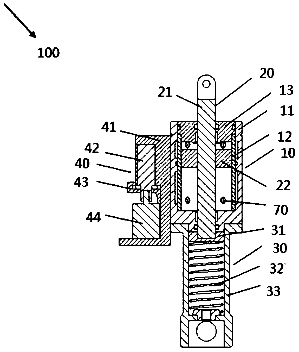
[0028] figure 1 It is a cross-sectional view of a key-shaped groove flow regulating damping cylinder for an intelligent knee joint in an embodiment of the present invention.

[0029] Such as figure 1 As shown, a key-groove flow regulating damping cylinder 100 for a smart knee joint in this embodiment has a cylinder portion 10 , a piston assembly 20 , a spring assembly 30 and a flow regulating assembly 40 .

[0030] The cylinder part 10 has a cylinder body 11 provided with two parallel hydraulic oil passages, a steel sleeve 12 fixed inside the cylinder body by a sealing ring, and a cylinder head 13 fixed on the upper end of the cylinder body 11 by threads.

[0031] The piston assembly 20 is disposed in the cylinder body 11 and has a piston rod 21 an...


PUM


Abstract

The invention provides a spline groove type flow rate adjusting damping cylinder for an intelligent knee joint. The spline groove type flow rate adjusting damping cylinder comprises a cylinder part, apiston assembly, a spring assembly and a flow rate adjusting assembly, wherein the cylinder part is provided with a cylinder body, a steel coat and a cylinder cover; the cylinder body is provided with two parallel hydraulic oil passages; the steel coat is fixedly arranged in the cylinder body by a sealing ring, and the cylinder cover is fixedly arranged at the upper end of the cylinder body through threads; the piston assembly is arranged in the cylinder body, and is provided with a piston rod and a piston, and the piston is sheathed on the piston rod through threads; the spring assembly is provided with a spring push block, an extending-assisting spring and a spring casing, the spring push block is fixedly connected with the lower end of the piston rod, the extending-assisting spring isarranged under the spring push block, and the spring casing is connected with the bottom end of the cylinder body and is used for accommodating the extending-assisting spring; the flow rate adjustingassembly is provided with an adjusting seat, an axial adjusting valve body, a stopper and a stepping motor, the adjusting seat is fixedly connected with the cylinder body, the upper part of the adjusting seat is provided with a cylindrical groove opening, the axial adjusting valve body is arranged on the adjusting seat through the cylindrical groove opening, the stopper is arranged on the adjusting seat and is used for fixing the axial adjusting valve body, the stepping motor is fixedly arranged at the bottom part of the adjusting seat, and the stepping motor is connected with the axial adjusting valve body.

Description

technical field [0001] The invention relates to a damping cylinder structure, in particular to a key-shaped groove type flow regulating damping cylinder for an intelligent knee joint. Background technique [0002] The smart knee joint refers to controlling the damper of the knee joint through a microcomputer to control the speed of the swing phase and the stability of the support phase at the same time, so that the gait of a lower limb patient is closer to that of a healthy person when wearing a prosthesis, with higher following and symmetry . At present, there are mainly three ways to adjust damping in smart knee joints: magneto-rheological, pneumatic and hydraulic. The magnetorheological smart knee joint adjusts the damping effect by changing the current to change the magnetic field strength, but the viscosity change of the magnetorheological fluid is closely related to the magnetic field, and it has high requirements on the material of the magnetorheological fluid, which...

Claims


Application Information

Patent Timeline
Patent Type & Authority Applications(China)
IPC IPC(8): A61F2/64A61F2/68
Inventor 喻洪流汪晓铭曹武警杨洁李慧肖艺璇孟巧玲李素姣
Owner UNIV OF SHANGHAI FOR SCI & TECH
Why Eureka
Try Eureka