Gas phase sample introduction bottle cleaning device

A technology for cleaning devices and sampling bottles, which is applied in the direction of cleaning hollow objects, cleaning methods and utensils, chemical instruments and methods, etc., can solve problems such as danger, time-consuming and laborious, and low work efficiency, and achieve compact structure, cost reduction, and improvement The effect of work efficiency

Active Publication Date: 2019-05-28
ELECTRIC POWER RESEARCH INSTITUTE OF STATE GRID SHANDONG ELECTRIC POWER COMPANY +2
View PDF2 Cites 0 Cited by
  • Summary
  • Abstract
  • Description
  • Claims
  • Application Information

AI Technical Summary

Problems solved by technology

During manual cleaning, laboratory personnel need to wear gas masks, and they need to be dried after cleaning. The whole cleaning process is not only time-consuming and labor-intensive, but also has low work efficiency and certain dangers.

Method used


Image

  • Gas phase sample introduction bottle cleaning device
  • Gas phase sample introduction bottle cleaning device
  • Gas phase sample introduction bottle cleaning device

Examples


Embodiment 1

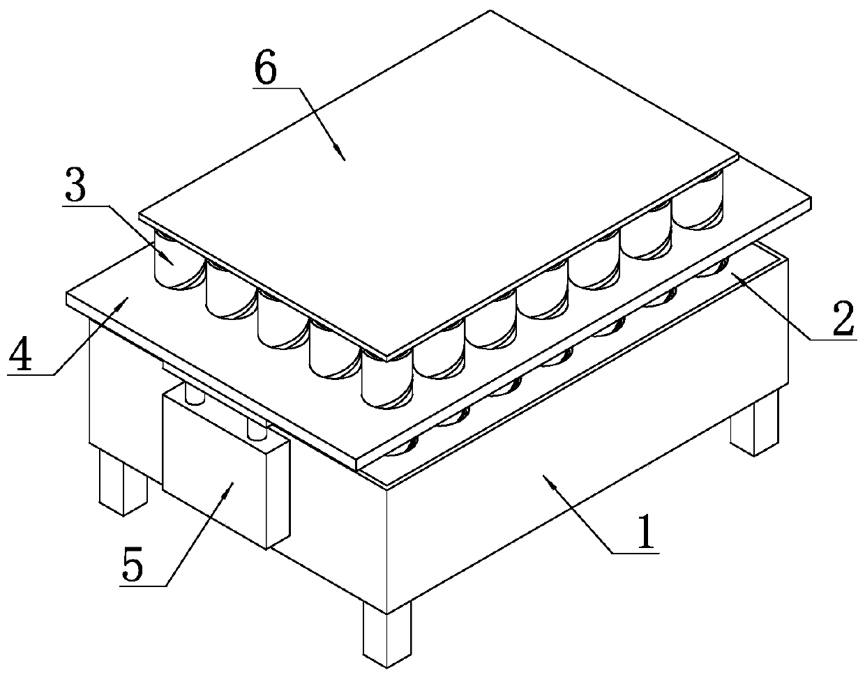
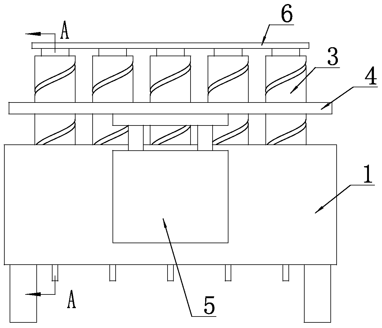
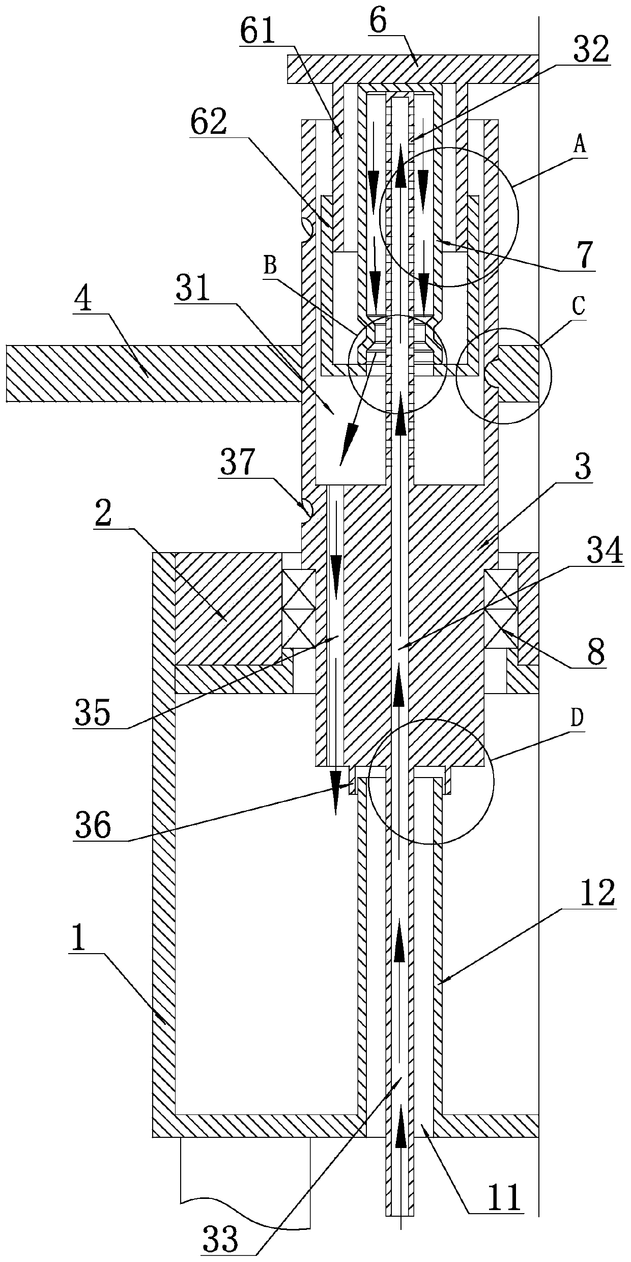
[0040] A device for cleaning a gas-phase sampling bottle 7 sequentially includes a cleaning unit and a fixing unit for fixing the gas-phase sampling bottle 7 from the bottom to the top.

[0041] like Figure 10 As shown, the fixing unit includes a fixing plate 6 , and a plurality of limit cylinders 61 for accommodating gas-phase sampling vials 7 are arranged on the lower side of the fixing plate 6 . As a specific implementation, there are 35 limiting cylinders 61 described in this embodiment, arranged in a matrix of seven rows and five columns. Each of the limiting cylinders 61 is provided with a compression cylinder 62 for compressing the gas phase sampling bottle 7 , and the compression cylinder 62 is threadedly connected to the limiting cylinder 61 . The compression cylinder 62 is provided with a first through hole 11, when the gas phase sampling bottle 7 is compressed in the limit cylinder 61, the mouth of the gas phase sampling bottle 7 passes through the first The thro...

Embodiment 2

[0057] The nozzle pipe 32, the drainage pipe 33 and the cleaning roller shaft 3 adopt a split structure, and the lower end of the nozzle pipe 32 is fixedly connected with the cleaning roller shaft 3 through a threaded connection, and the drainage pipe 33 The upper end is fixedly connected with the cleaning roller shaft 3 through threaded connection. All the other structures are the same as in Embodiment 1.


PUM


Abstract

The invention discloses a gas phase sample introduction bottle cleaning device. The gas phase sample introduction bottle cleaning device comprises a cleaning unit and a fixing unit from bottom to topin sequence, wherein the fixing unit is used for fixing gas phase sample introduction bottles. The cleaning unit comprises a waste liquor box, at least two cleaning roller shafts, a driving plate fordriving the cleaning roller shafts to rotate, and an air cylinder for driving the driving plate to move up and down. The waste liquor box is internally provided with an installation plate, and the cleaning roller shafts are arranged on the installation plate and rotationally connected with the installation plate. The upper ends of the cleaning roller shafts are provided with cleaning grooves, andthe bottom surfaces of the cleaning grooves are provided with spray pipes and water discharging holes. The lower ends of the cleaning roller shafts are provided with drainage tubes, and the drainage tubes are connected with a liquor supply unit through rotating joints. The cleaning roller shafts are internally provided with flow guide holes for communicating with the drainage tubes and the spray pipes. The gas phase sample introduction bottle cleaning device can conduct batch cleaning on the gas phase sample introduction bottles, and the working efficiency is greatly improved.

Description

technical field [0001] The invention relates to a cleaning device, in particular to a cleaning device for gas-phase sampling bottles. Background technique [0002] At present, when detecting organic poisons in the air of the workplace, activated carbon tubes or silica gel tubes are generally used for sampling, and then carbon disulfide or methanol is used for desorption, followed by gas chromatography for detection. In this way, a large amount of carbon disulfide, methanol, etc. will remain in the gas-phase sampling bottle after use, which needs to be cleaned. Carbon disulfide has a strong odor and is toxic. During manual cleaning, laboratory personnel need to wear gas masks, and they need to be dried after cleaning. The whole cleaning process is not only time-consuming, labor-intensive, and inefficient, but also has certain risks. Contents of the invention [0003] In view of the above problems, the present invention provides a gas-phase sampling bottle cleaning device,...

Claims


Application Information

Patent Timeline
IPC IPC(8): B08B9/093B08B13/00B08B9/087
Inventor 巩泉泉窦丹丹王胜锋马新刚刘辉臧玉魏张永谢连科江红尹建光王坤张国英张兆波陈超崔相宇
Owner ELECTRIC POWER RESEARCH INSTITUTE OF STATE GRID SHANDONG ELECTRIC POWER COMPANY
Why Eureka
Try Eureka