Machining method of micropore polyurethane sealing ring and tool clamp used for method

A technology of fixtures and processing methods, which is applied in the field of polyurethane materials, can solve problems such as low production efficiency and finished product qualification rate, poor exhaust, and difficulty in large-scale production, and achieve the goal of improving production efficiency and yield, and high-efficiency processing methods Effect

Pending Publication Date: 2019-05-28
洛阳凯众减震科技有限公司
View PDF0 Cites 0 Cited by
  • Summary
  • Abstract
  • Description
  • Claims
  • Application Information

AI Technical Summary

Problems solved by technology

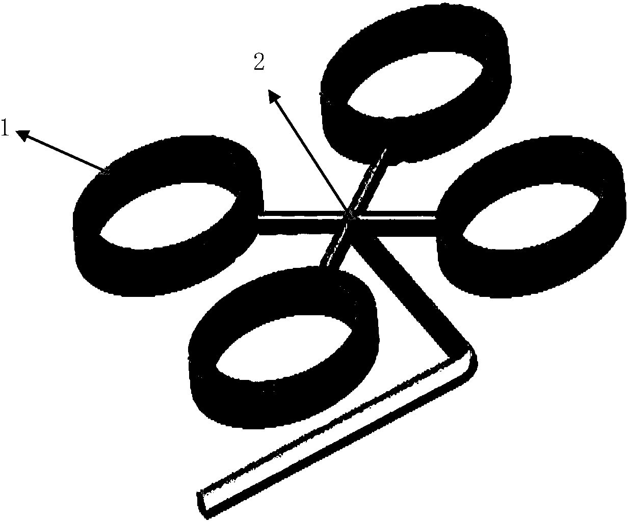
Taking one mold with four cavities as an example, each product is connected to the sprue 2 when the product is released from the mold, such as figure 1 As shown, in this way, when the product is separated from the runner 2, a gate will be formed on each product, and it needs to be trimmed. However, after trimming, the gate of the product surface will often have rough and uneven defects; in addition, There may also be poor exhaust at the edge of each product, resulting in air bubbles
Therefore, this general multi-cavity mold casting method has extremely low production efficiency and finished product qualification rate (50-60% yield), and the number that can be produced in one mold is usually only 4-6 due to the limitation of the molding equipment structure. Moreover, the sprue accounts for a large proportion, and the utilization rate of raw materials is low, so it is difficult to form large-scale production

Method used


Image

  • Machining method of micropore polyurethane sealing ring and tool clamp used for method
  • Machining method of micropore polyurethane sealing ring and tool clamp used for method
  • Machining method of micropore polyurethane sealing ring and tool clamp used for method

Examples


Embodiment Construction

[0033] In order to have a more specific understanding of the technical content, features and effects of the present invention, the technical solution of the present invention will be further described in detail with reference to the accompanying drawings and specific embodiments.

[0034] The processing method of the microporous polyurethane sealing ring of this embodiment includes the following steps:

[0035] Step 1. Use a low pressure polyurethane injection machine to mix the microporous polyurethane liquid raw materials (usually A and B two-component materials, A material is usually polymerized polyol, and B material is usually isocyanate or isocyanate prepolymerized Body), composed of two mold halves (mold temperature 40~80℃, structure like figure 2 Shown) The bottom is injected into the two halves of the mold cavity, foamed for 5-10 minutes, then the mold is opened, and the microporous polyurethane blank casting is removed from the core to obtain image 3 The cylindrical micr...


PUM

PropertyMeasurementUnit
thicknessaaaaaaaaaa

Abstract

The invention discloses a machining method of a micropore polyurethane sealing ring. The method comprises the steps of producing a micropore polyurethane hollow casting and cutting the micropore polyurethane hollow casting into the micropore polyurethane sealing ring. The invention further discloses a turning-lathe tool clamp used for the method. The tool clamp comprises a core rod and a supporting shaft, the core rod is cylindrical, and the supporting shaft is in a ring columnar shape, and coats the core rod. The cylindrical micropore polyurethane hollow casting is subjected into injection molding, a thin blade turning knife tool or numerical control automatic turning lathe is used for cutting the micropore polyurethane hollow casting into the needed-size seal ring, the production efficiency and the yield of the micropore polyurethane sealing ring are improved, and the more efficient machining method is provided for large-scale production of the micropore polyurethane sealing ring.

Description

Technical field [0001] The invention relates to the field of polyurethane materials, in particular to the processing of microporous polyurethane sealing rings. Background technique [0002] Due to its excellent sealing and durability, microporous polyurethane elastomers are often used as sealing materials for dust and seepage prevention. The production of microporous polyurethane sealing ring from microporous polyurethane usually adopts the method of casting and direct molding with general multi-cavity mold. Take one mold with four cavities as an example. When the product is ejected from the mold, each product is connected to runner 2, such as figure 1 As shown, in this way, when the product is separated from the runner 2, each product will have a gate, which needs to be trimmed, but after trimming, the surface of the product often has defects such as unevenness and unevenness at the gate; in addition, Poor venting may also occur at the edge of each product, resulting in bubbles...

Claims


Application Information

Patent Timeline
Patent Type & Authority Applications(China)
IPC IPC(8): B23B29/26B23B27/00B29C44/02
Inventor 庞建军武应涛
Owner 洛阳凯众减震科技有限公司
Why Eureka
Try Eureka