Material holding device and material detection method

A material detection and holding device technology, used in workpiece holding devices, measuring devices, instruments, etc., can solve the problems of multiple manual operations, obstacles, and large operation repeatability, and achieve the effect of improving work efficiency.

Active Publication Date: 2021-11-05
SHANGHAI MICRO ELECTRONICS EQUIP (GRP) CO LTD
View PDF17 Cites 0 Cited by
  • Summary
  • Abstract
  • Description
  • Claims
  • Application Information

AI Technical Summary

Problems solved by technology

[0008] It can be seen from this that the traditional detection mode requires more manual operations and the operation is highly repeatable. Due to the large number of detection times, multiple repeated operations are required, which greatly reduces the work efficiency of the detection production line. Work has a great hindrance

Method used


Image

  • Material holding device and material detection method
  • Material holding device and material detection method
  • Material holding device and material detection method

Examples


Embodiment Construction

[0048] In the following description, numerous specific details are set forth in order to provide a thorough understanding of the present invention. However, the present invention can be implemented in many other ways different from those described here, and those skilled in the art can make similar extensions without violating the connotation of the present invention, so the present invention is not limited by the specific embodiments disclosed below.

[0049] In the following, specific embodiments of the present invention will be described in conjunction with the accompanying drawings. see Figure 1-6 As shown, the present invention provides a material holding device.

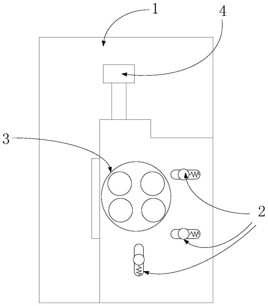
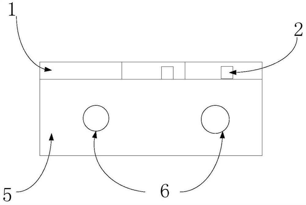
[0050] Such as figure 2 and 3 A top view and a side view of a material holding device according to an embodiment of the present invention are shown respectively. The material holding device is mainly composed of a positioning plate 1, a material fixing mechanism, and an adapter board 54 ( Figure 4 ), th...


PUM


Abstract

The invention provides a material holding device and a material detection method. The material holding device includes a positioning plate, a material fixing mechanism, an adapter board, a base, and a universal interface. The positioning plate is arranged on the base, wherein The base is provided with a general interface to realize docking with external detection equipment; the adapter board is used to connect the detection interface of the material with the external detection equipment. Automatic and rapid docking with external detection equipment is realized through the general interface of the material holding device, and when the material holding device clamps and moves the material, it can realize clamping without connecting with external equipment, which improves the Check the efficiency of the production line.

Description

technical field [0001] The invention relates to the field of microelectronic equipment, in particular to a material holding device and a material detection method. Background technique [0002] In the microelectronic equipment manufacturing industry, it is usually necessary to use various machines to perform a series of processing, moving and testing operations on the workpiece. The operation needs to clamp and position the workpiece before processing and testing. [0003] In the production of microelectronic products, generally in order to ensure the quality of products or semi-finished products, it is necessary to conduct defect detection (such as OTP detection, electrical inspection, etc.) on products (materials). The flow chart of the assembly line for material detection is as follows: figure 1 Shown: First, the detection object (hereinafter also referred to as "material") is transferred from the transmission device to A for clamping, and connected with the detection d...

Claims


Application Information

Patent Timeline
Patent Type & Authority Patents(China)
IPC IPC(8): B25B11/00G01D21/00
Inventor 卢彧文王璟周畅廖飞红徐健
Owner SHANGHAI MICRO ELECTRONICS EQUIP (GRP) CO LTD
Why Eureka
Try Eureka